Series and Shunt Compensation of Transmission Lines:
The performance of long EHV AC transmission systems can be improved by reactive compensation of series or shunt (parallel) type. Series capacitors and shunt reactors are used to reduce artificially the series reactance and shunt susceptance of lines and thus they act as the line compensators. Series and Shunt Compensation of Transmission Lines results in improving the system stability and Voltage Control Method, in increasing the efficiency of power transmission, facilitating line energization and reducing temporary and transient overvoltages.
Series compensation reduces the series impedance of the line which causes voltage drop and is the most important factor in finding the maximum power transmission capability of a line (Eq. (5.70)). A, C and D constants are functions of Z and therefore the also affected by change in the value of Z, but these changes are small in comparison to the change in B as B = Z for the nominal -π and equals Z (sinh γ1/γ1) for the equivalent π.
The voltage drop ΔV due to series compensation is given by
![]()
Here XC = capacitive reactance of the series capacitor bank per phase and XL is the total inductive reactance of the line/phase. In practice, XC may be so selected that the factor (XL — XC) sin Φr becomes negative and equals (in magnitude) R cos Φr so that ΔV becomes zero. The ratio XC/XL is called “compensation factor” and when expressed as a percentage is known as the “percentage compensation“.
The extent of series and shunt compensation of transmission lines depends on the number, location and circuit arrangements of series capacitor and shunt reactor stations. While planning long-distance lines, besides the average degree of compensation required, it is required to find out the most appropriate location of the reactors and capacitor banks, the optimum connection scheme and the number of intermediate stations. For finding the operating conditions along the line, the ABCD constants of the portions of line on each side of the capacitor bank, and ABCD constants of the. bank may be first found out and then equivalent constants of the series combination of line-capacitor-line can then be arrived at by using the formulae.
In India, in states like UP, series compensation is quite important since super thermal plants are located (east) several hundred kilometers from load centres (west) and large chunks of power must be transmitted over long distances. Series capacitors also help in balancing the voltage drop of two parallel lines.
When series compensation is used, there are chances of sustained overvoltage to the ground at the series capacitor terminals. This overvoltage can be the power limiting criterion at high degree of compensation. A spark gap with a high speed contactor is used to protect the capacitors under overvoltage conditions.
Under light load or no-load conditions, charging current should be kept less than the rated full-load current of the line. The charging current is approximately given by BC|V| where BC is the total capacitive susceptance of the line and |V| is the rated voltage to neutral. If the total inductive susceptance is B1 due to several inductors connected (shunt compensation) from line to neutral at appropriate places along the line, then the charging current would be
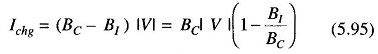
Reduction of the charging current is by the factor of (1 — B1/BC) and B1/BC is the shunt compensation factor. Shunt compensation at no-load also keeps the receiving end voltage within limits which would otherwise be quite high because of the Ferranti Effect. Thus reactors should be introduced as load is removed for proper voltage control.
As mentioned earlier, the shunt capacitors are used across an inductive load so as to provide part of the reactive VARs required by the load to keep the voltage within desirable limits Similarly, the shunt reactors are kept across capacitive loads or in light load conditions, as discussed above, to absorb some of the leading VARs for achieving voltage control. Capacitors are connected either directly to a bus or through tertiary winding of the main transformer and are placed along the line to minimise losses and the voltage drop.
It may be noted that for the same voltage boost, the reactive power capacity of a shunt capacitor is greater than that of a series capacitor. The shunt capacitor improves the pf of the load while the series capacitor has hardly any impact on the pf Series capacitors are more effective for long lines for improvement of system stability.
Thus, we see that in both series and shunt compensation of transmission lines it is possible to transmit large amounts of power efficiently with a flat voltage profile. Proper type of series and shunt compensation of transmission lines should be provided in proper quantity at appropriate places to achieve the desired Voltage Control Method.