Controlled Transistor Series Regulator with Short Circuit Protection:
Controlled Transistor Series Regulator with Short Circuit Protection – If the load resistance RL is reduced or load terminals are shorted accidentally, a very large load current will flow in the circuit shown in Fig. 43.6. It may destroy the pass transistor Q1, diode or possibly some other component. Fuse protection will not prove adequate because the transistor may get damaged in a very small fraction of a second.
![]()
To avoid this situation, a current limiting circuit is added to a series regulator, as illustrated in Fig. 43.7.
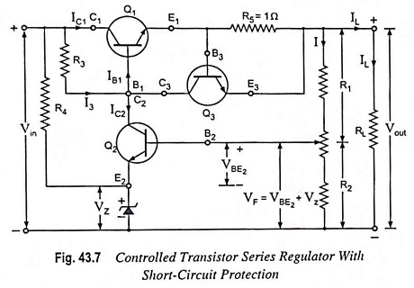
The current limiting circuit consists of a transistor Q3 and a resistor R5 (approximately 1 Ω) connected between base and emitter terminals of transistor Q3. With normal load current, transistor Q3 remains off because the voltage drop across resistor R5 is small (less than about 0.7 V necessary for making the transistor Q3 on). Under this condition, the circuit works normally, as described earlier. With the excessive load current (exceeding 0.6/1 i.e., 0.6 A or 600 mA) the voltage drop across R5 becomes large enough to turn transistor Q3 on. The collector current of transistor Q3 flows through R3 thereby decreasing the base voltage of transistor Q1. This results in reduction of the conduction level of transistor Q1. Thus further increase in load current is prevented.
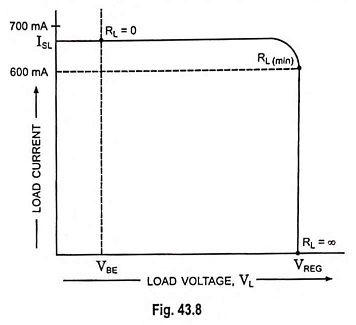
Figure 43.8 summarizes the current limiting. When load resistance RL is infinite, the output voltage is regulated and has a value of VREG. The load current IL is zero for this operating condition. When RL decreases, the load current IL increases up to the point where RL becomes equal to RL (min). At this minimum load resistance, IL equals 600 mA and VBE equals 0.6 V. Beyond this point, transistor Q3 turns on and the current limiting sets in. Further decrease in RL produces decrease in output voltage, and regulation is lost. When RL is zero, the load current IL is limited to a value between 600 mA and 700 mA. The load current with shorted load terminals is symbolized as ISL. When the load terminals are shorted in Fig. 43.7, the voltage across resistor R5 is
![]()
where VBE is typically between 0.6 a nd 0.7 V.
The minimum load resistance where regulation is lost can be estimated with the following equation
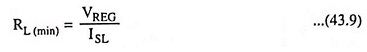
The exact value of RL (min) will be slightly less or greater than this.
The simple current limiting circuit also has a drawback of large power dissipation across the series pass transistor. With a short across the load, almost all the input voltage appears across the pass transistor. So the pass transistor has to dissipate approximately
![]()
where VBE is the base-emitter voltage of Q3, the current-limiting transistor.