Two phase AC Servo Motor:
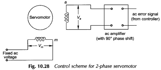
For a low-power (a few hundred watts) control application, a balanced Two phase AC Servo Motor is ideally suited as it can be driven by means of a relatively rugged (drift-free) ac amplifier. The motor torque can be easily controlled by varying the magnitude of the ac voltage applied to the control phase (phase a) of the motor as shown in Fig. 10.28. While the second phase called the reference phase (phase m) is excited at a fixed-voltage synchronous ac voltage (both the voltages must be drawn from the same source). The control phase voltage is shifted in phase by 90° from the reference phase voltage by means of phase-shifting networks included in voltage amplification stages of the amplifier. The motor torque gets reversed by phase reversal of the control phase voltage.
For linear stable operation, the torque-speed characteristic of a Two phase AC Servo Motor must be linear with negative slope (torque reducing with increasing speed). The torque-speed characteristic of a normally designed induction motor is highly nonlinear and the characteristic is unstable for normal loads in the region from zero speed to speed at breakdown torque. This indeed is the useful region of operation of a Two phase Servomotor employed in position control systems. The desired linear characteristic is obtained in a servo motor by designing a rotor with high resistance so that the maximum torque occurs at a slip of – 0.5 or so. The high resistance also imparts another important desirable feature to the servomotor, i.e. it does not develop a single-phasing torque which would disturb the control characteristic of the motor.
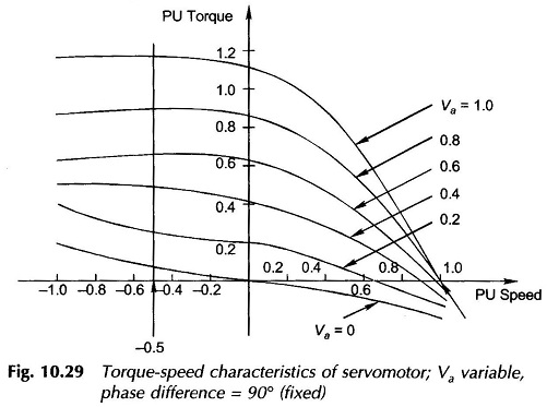
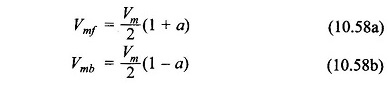
The torque-speed characteristics of a Two phase AC Servo Motor for various per unit values of phase a voltage are drawn in Fig. 10.29. If the reference phase voltage is Vm ∠ 0°, the control phase voltage is
![]()
Now
Thus the motor is excited with a special kind of voltage unbalance—angular phase difference of 90° is maintained while the magnitude of phase a voltage varies. The corresponding torque-speed characteristics (Fig. 10.29) are nearly linear with respect to motor speed and voltage of phase a.
Based on the linearity assumption, the following relation is obtained
![]()
where
- ω = rotor speed
Also
![]()
where
- J= motor inertia, and
- fo = motor viscous friction.
Laplace transforming Eq. (10.59a) and (10.59b), the motor transfer function can be written as
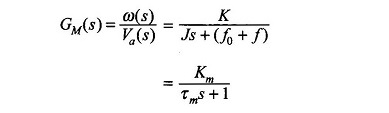
where
- Km = K/(f0 + f) = motor gain constant
- τm = J/(f0 + f) = motor time-constant
In Two phase AC Servo Motor of rating below a few watts, low-inertia construction can be achieved by using a drag-cup rotor illustrated in Fig. 10.30. It is to be observed that the rotor core is stationary.
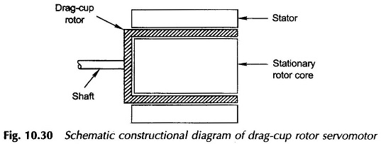
Ac servomotor offers several advantages over its dc counterpart—the use of a drift-free ac amplifier in control circuitry, low rotor inertia (faster response), rugged maintenance-free rotor construction, no brushes contacting commutator segments, etc. The rotor can withstand higher temperature as it does not involve any insulation.
Two Phase AC Tachometer:
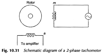
Ac (carrier) control systems usually require a feedback signal of carrier frequency whose amplitude is proportional to speed. Such signals are conveniently obtained by means of ac tachometers. An ac tachometer is nothing but a 2-phase induction motor with one phase (m) excited from the carrier frequency, while the phase a winding is left open-circuited as shown in Fig. 10.31. To achieve a low-inertia, a rotor drag-cup construction is commonly employed. It is shown below that the voltage across phase a is proportional to rotor speed while it has phase shift close to 90°).
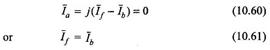
For a balanced 2-phase winding
![]()
With the phase a open-circuited
Therefore

Also
![]()
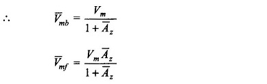
Now
Since Z̅f (total) and Z̅b (total) are speed (slip) dependent, so is A̅z. This Va is speed dependent. If the rotor X2/R2 is either very small or very large, it is discovered that Va – speed relationship is linear. Low X2/R2 gives low speed sensitivity but a wide linear range and vice versa. An intermediate value of X2/R2 generally meets most of the specifications. The phase shift is slightly less than 90° but is quite insensitive to speed.
AC tachometers are quite commonly used in 400-Hz control systems. High precision construction is required to maintain concentricity and to prevent any direct coupling between the two phase windings. Pick-up from stray fields is eliminated by soft-iron shields.