Single Phase Separately Excited DC Motor Drives:
The circuit arrangement of a Single Phase Separately Excited DC Motor Drives Drives fed from a single phase controlled converter is shown in Fig. 4.56. The block 1 can be any one of the single phase converters.
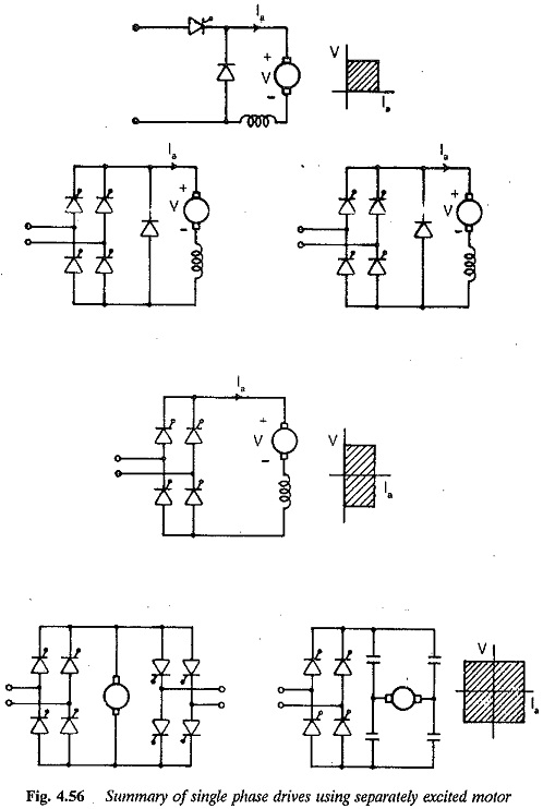
Half wave drives: The Single Phase Separately Excited DC Motor Drives is supplied from a single phase half wave circuit (Fig. 4.56(a)). Low cost and simplicity are the advantages of this drive. This can provide only one quadrant operation. Regeneration is not possible. The conduction angle of the thyristor is very small, resulting in a very low average current. The torque developed is very small resulting in a loss of torque at the rated rms current. The rms to average current ratio is also more. The motor current is always discontinuous. The ripple frequency is equal to supply frequency. The current and voltage wave forms are shown in Fig. 4.57.
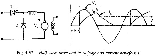
The freewheeling diode across the load improves the performance. The speed regulation is very poor. At low speeds the motor receives power in pulses and the motor may chug when the load is high. The speed oscillation is quite high. The supply transformer has premagnetisation due to dc component of the load current. The application of this drive is limited to low powers.
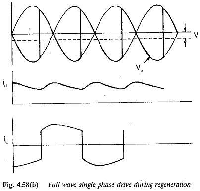
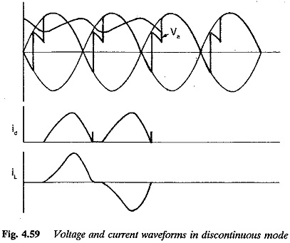
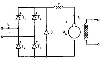
Full wave drives: The Single Phase Separately Excited DC Motor Drives is supplied by a full wave converter. A full wave drive using a fully controlled converter is shown in Fig. 4.56(b). The wave forms of voltage and current in the load are shown in Fig. 4.58. Having thyristors in all positions, the firing of the thyristors allows negative average voltages, making the power flow from load to the supply. The motor can be braked effectively using regenerative braking. This can be made possible at constant current. As the load current flows both during positive and negative half cycles, the average value of the current is more than that in the half wave drive. The torque capability increases for a given armature heating. The ratios of peak to average and rms to average are better here. The speed oscillation is less. The speed regulation improves because of increased conduction of current in the load. The number of pulses are two and pulse frequency in the load is 2f. The ripple amplitude is smaller in this case. The speed oscillations are decreased. The discontinuous conduction is present and the wave forms for this case are shown in Fig. 4.59. This affects the speed regulation. An additional inductance in the’ armature improves the performance. It reduces the ripple content, reduces the possibility of discontinuous conduction, im¬proves speed regulation, etc. This inductance also affects the performance of the drive on the line side. The harmonic content of the line current is more at lower values of inductance because of possible discontinuous load current. As the inductance increases the harmonic factor decreases. The peak value of current decreases with additional inductance. This improves the commutating capability.
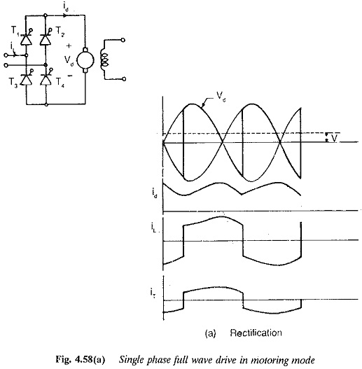
The motor may be designed with a high value of armature inductance. Otherwise extra inductance occupies space. Inductance has no effect on the fundamental displacement factor. There can be slight improvement in the power factor as the harmonic factor is affected by this inductance. The serious drawback with a fully controlled converter is poor power factor.
A full wave drive fed from a semi converter is depicted in Fig. 4.56(c).
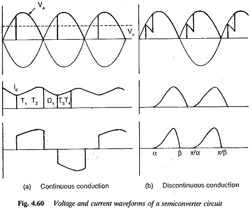
The wave forms of voltage and current are shown in Fig. 4.60. A reference to Fig. 4.60 shows that the supply current is in pulses and flows for (π-α) This is due to the natural freewheeling provided by the diodes to maintain the load current. The supply does not provide current during freewheeling. This has the distinct advantage, compared to a fully controlled drive, that the fundamental displacement factor of the line current is better. However, as the speed decreases, i.e., as the firing angle is delayed, the fundamental displacement factor decreases. A semi converter drive shows an increased harmonic content at low speeds. This is again due to the dependence of the width of the current pulse on firing angle. The peak value is less due to freewheeling. This improves the commutating capability of the motor, particularly at low speeds and light loads. The rms current is also less in a semi converter, which reduces motor heating compared to a fully controlled one. The heating of the motor is 44% less. Discontinuous conduction is present at light loads and low speeds and this causes a speed regulation poorer than the full converter. The freewheeling does not allow negative excursions of the load voltage and therefore negative average voltage is not possible. Hence, a semi converter is used with one quadrant drive where no regeneration is required. The advantages of improved power factor, better commutating capability and low cost due to diodes makes a semi converter drive applicable to all cases where regeneration is not required.
The saving of reactive power and hence improvement in the fundamental displacement factor can be achieved by a full converter with a freewheeling diode. The schematic diagram of the converter feeding a Single Phase Separately Excited DC Motor Drives is shown in Fig. 4.56(c). The diode provides an alternative path for the load current and provides the same effects as in a semi converter. The freewheeling diode is effective in the complete speed range. The diode does not allow negative voltages of the load and hence there is no regeneration.
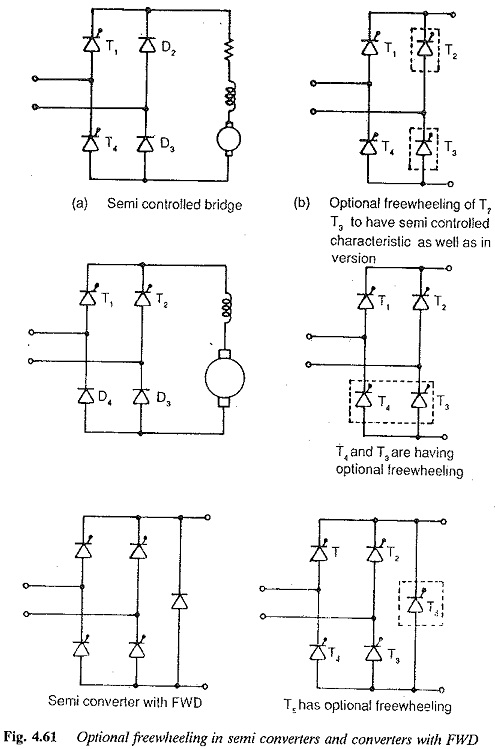
It is possible to have the regeneration mode besides the advantages mentioned above during rectification by having thyristors with optional freewheeling. Two thyristors (T2, T4 for symmetrical connection; T3, T4 for unsymmetrical connection) of a fully controlled converter are fired at α = 0 so that they act as diodes to provide freewheeling during rectification (Fig. 4.61). During inversion they are operated as normal ihyristors. The freewheeling diode is also replaced by a thyristor which is fired at a = 0 when freewheeling is required and is blocked when it is not required. This optional freewheeling provides all the advantages of one quadrant converters as well as making inversion possible. However it may be noted that these advantages are not present during inversion.