Derivation of Single Phase Quantity from Three Phase System:
It will be seen later that auxiliary channels or pilot wires are used to transmit information from one end of the line to the other end. For a normal three-phase system three pilots would ordinarily be required which would obviously be a very costly affair for longer systems, particularly transmission circuits. It would naturally be preferable to have a means of deriving a single-phase quantity which under both normal and abnormal conditions will be representative of the three-phase conditions. Sometimes it becomes necessary to segregate the sequence currents or voltages from corresponding line currents or voltages in order to simplify the protection scheme by reducing the number of relays required. There are two commonly used methods for Derivation of Single Phase Quantity from Three Phase System
(a) Summation Transformers: The three line current transformers (CTs) are connected to the primary of an auxiliary current transformer (summation transformer) as shown in Fig. (2. 8). Each line CT energizes a different number of turns on the primary with a resulting single-phase output from the secondary. Thus for the typical case shown in Fig. (2.8) the output is seen to be proportional to the vector sum
![]()
It is also possible to control independently the outputs for earth faults and phase faults. The output on earth faults is usually considerably more than that on phase faults so as to provide more sensitive action on earth faults. Consequently, the pickup setting can be expressed in terms of combinations of n and 1 for the various faults.
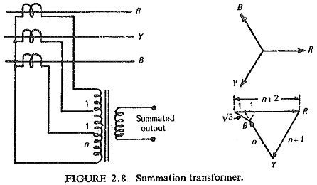
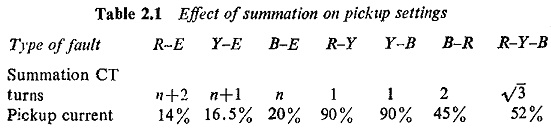
Table 2.1 shows the output current for a given fault current magnitude in each type of fault in terms of the rated current of CT.
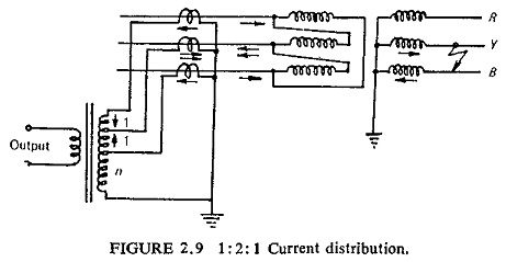
Zero output or a negligibly small output may occur under through fault conditions when there is a phase-to-phase fault on the star side of the delta/star transformer giving a 1: 2: 1 current distribution in the protected feeder as shown in Fig. (2.9). In general, however, it is possible to choose tappings which make such cases very unlikely.
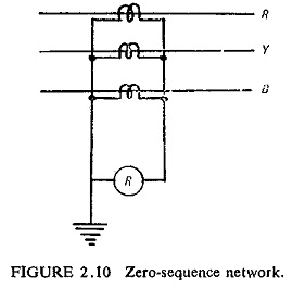
(b) Sequence Networks: In some cases it is desirable to make the protection respond to a particular phase-sequence component of the three-phase system of currents or voltages. Zero-sequence and negative-sequence networks are frequently used in power system protection.
Zero-sequence networks are extensively used for earth fault protection. The connections of such a network are shown in Fig. (2.10). During normal operation and for three-phase and phase-to-phase faults the current passing through the relay is zero. When a single or double earth fault occurs, the zero-sequence current flows through the relay.
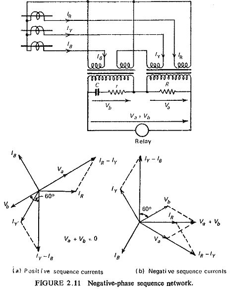
For unbalanced conditions or unsymmetrical faults negative-phase sequence networks are used. One simple negative-sequence network is shown in Fig. (2.11). The values of r and C are such as to give a phase shift of 60°. It can be seen from the vector diagrams that for the positive-sequence currents the output voltage Va + Vb applied to the relay is zero whereas for the negative-sequence currents the output voltage Va + Vb is of considerable magnitude to operate the relay.
However protection responding to positive-phase sequence components alone is not used in relaying practice, because under unsymmetrical faults, such a protection will have less sensitivity due to the fact that the positive-phase sequence component is only a part of the fault current.
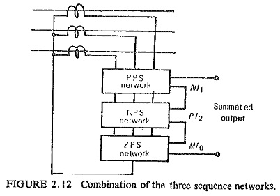
It is possible however to use a combination of the positive-sequence, negative-sequence and zero-sequence networks as a general rule as shown in Fig. (2.12). A combination of positive and negative sequence networks is more common.