Feedback Amplifier – Block Diagram, Definition, Operation and Types:
Figure 19.7 represents the block diagram of an Feedback Amplifier. The output quantity (either voltage or current) is sampled by means of a suitable sampling network (or sampler) and is fed to the feedback network. The output of feedback network, which has a fraction of output signal is combined with the external (source) signal through a mixer network and fed into the basic amplifier.
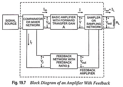
The different blocks of feedback amplifier are explained below:
1. Signal Source : This block is either a signal voltage Vs in series with a resistor Rs or a signal current Is in parallel with a resistor Rs.
2. Feedback Network : The feedback network is usually in the form of a passive two-port network and may be formed of resistors, inductor and capacitors (most often of resistors). Its function is to return a function of the output energy (voltage or current) to the input of the amplifier.
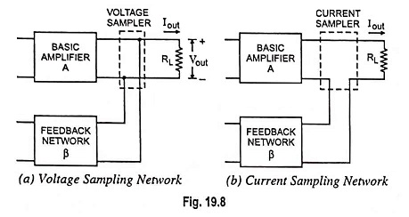
3. Sampling Network : Sampling networks are of two types, namely, voltage sampling network and current sampling network, as shown in Fig. 19.8. Output voltage is sampled by connecting the feedback network either shunt across the output or in series with the output. The former is known as voltage or node sampling [Fig. 19.8 (a)] and the latter is known as the current or loop sampling [Fig. 19.8 (b)].
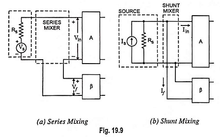
4. Comparator, or Mixer, Network : Mixer, also known as comparator, is of two types, namely, series mixer and shunt mixer, as shown in Fig. 19.9. A differential amplifier, which has two inputs and one output proportional to difference between the signals at the two inputs, is usually used as a mixer or comparator.
Types of Feedback Connections:
Any of the output connections shown in Fig. 19.8 may be combined with any of the input connections shown in Fig. 19.9 to form the feedback amplifier shown in Fig. 19.7. The resulting feedback amplifier topologies are given below :
- Voltage-series feedback, as shown in Fig. 19.10 (a).
- Voltage-shunt feedback, as shown in Fig. 19.10 (b).
- Current-series feedback, as shown in Fig. 19.10 (c).
- Current-shunt feedback, as shown in Fig. 19.10 (d).
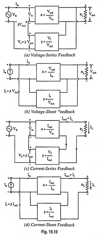
In the list above, voltage refers to connecting the output voltage as input to the feedback network and current refers to tapping off some output current through the feedback network. Series refers to connecting the feedback signal in series with the input signal voltage; and shunt refers to connecting the feedback signal in parallel (shunt) with an input current source.
Series feedback connections tend to increase the input impedance of the amplifier. This is because in this case feedback signal is returned to the input in series to oppose the applied voltage causing input current to fall and consequently makes the input impedance to increase. In case of shunt or parallel connections, the current drawn from the signal source is increased by an amount equal to feedback current If and therefore, input impedance falls. Voltage feedback tends to reduce the output impedance while current feedback tends to increase the output impedance. In cascaded amplifiers, mostly high input impedance and low output impedance are desired. Both of these (i.e., high input impedance and low output impedance) are provided by use of voltage-series feedback and so it is most commonly employed.
Transfer Ratio or Gain:
The symbol A in Fig. 19.7 represents the ratio of the output signal to the input signal of the basic amplifier. The transfer ratio Vout/Vin, referred to as voltage gain Av, the transfer ratio Iout/Iin, referred to as current gain Ai, the ratio Iout/Vin, referred to as the transconductance Gm, and the ratio Vout/Iin, referred to as the transresistance Rm, are referred to as a transfer gain of the basic amplifier without feedback and represented by symbol A.
The symbol Af defined as the ratio of the output signal to the input signal of the amplifier configuration shown in Fig. 19.7, is shown as the transfer gain of the amplifier with feedback. Thus, Af is used to represent any one of the four ratios Vout/Vs = Avf, Iout/Is = Aif, Iout/Vs = Gmf and Vout/Is = Rmf.