Radio Communication System – Block Diagram and types:
Radio communication is very popular technique of communicating a message. The radio waves are electromagnetic waves produced due to escape of electrical energy into free space. They have a frequency range from a few hertz to gigahertz. They travel with a velocity of light i.e., 3 x 10⁸ m/s and consist of electric and magnetic fields at right angles to each other. The basic elements of a radio communication system are shown in Fig. 22.57. For the sake of convenience, the entire arrangement can be divided into three components viz. transmitter, transmission of electromagnetic waves and radio receiver.
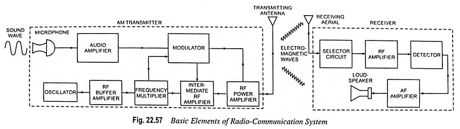
1. Transmitter: The function of transmitter is to generate radio communication waves for transmission into space. The important components of an AM transmitter are shown in a dashed block in Fig. 22.57. The individual components are described as below:
- Microphone is a device that converts sound waves into electrical waves. The air pressure, produced due to voice, music or code, on the diaphragm of a microphone generates an audio electrical signal corresponding in frequency to the original signal. The output of the microphone is supplied to a multistage audio amplifier.
- Audio amplifier is to strengthen the audio signal received from the microphone. The amplified output from the audio amplifier is fed to the modulator.
- Oscillator is a crystal controlled type. Its function is to generate a high frequency signal, called the carrier wave. The power output of the oscillator is not large and, therefore, needs strengthening.
- RF buffer amplifier is meant for isolating the oscillator from succeeding stages so that the loading effect does not occur.
- Frequency multiplier is meant for multiplying the frequency of the oscillator output so as to raise to the required value. The crystal oscillator is not capable of generating high frequency required for carrier wave and therefore, needs multiplication.
- Modulator: The amplified audio signal and carrier wave are fed to the modulator. Here, the audio signal is superimposed on the carrier wave in a suitable manner. The resultant waves are known as modulated waves or radio waves.
- Intermediate RF amplifier is meant for amplification of modulator output, in case of low level modulation.
- RF power amplifier is meant for amplifying the modulated carrier before being fed to the antenna for transmission. For high level modulation, the modulator output is applied to the final RF amplifier.
2. Transmission of Radio Waves: The radio waves from the transmitter are fed to the transmitting antenna (or aerial) from where these are radiated into space. The radio waves are electromagnetic waves and have the same general properties. These are similar to light and heat waves except that they have longer wavelengths.
AM Radio Receivers: On reaching the receiving aerial, the radio waves induce tiny emf in it. This small emf is supplied to the radio receiver where the radio waves are first amplified and then audio signal is extracted from them by the process of detection. The audio signal is amplified by the audio amplifier and then fed to the speaker for sound reproduction. Thus radio receiver is a complete device that receives the modulated radio waves from the receiving antenna or aerial, detects, amplifies and makes us listen the signal or information. In India, since the broadcast is only amplitude modulated, the receivers are also of AM detection type and called the AM radio receivers. Broadly, there are two types of receivers viz. straight radio receivers and superheterodyne receivers.
(a) Straight Radio Receiver: The important components of a straight radio receiver are shown in a dashed block in Fig. 22.57. The individual components are described below:
- Selector Circuit: Antenna receives various modulated signals of different frequencies from various stations and the desired frequency is to be tuned in. This is accomplished by a selector circuit which is a parallel resonant circuit and by varying the capacitance of the circuit, resonance at the desired frequency can be obtained. Thus the desired carrier is selected and the other carriers that may be reaching antenna are rejected.
- RF Amplifier: The selected radio communication (carrier along side-bands) is amplified by RF amplifier and then fed to the detector.
- Detector is meant for detecting the envelope of the modulated carrier after amplification.
- AF amplifier is meant for amplifying the detected audio frequency signal containing the intelligence and then fed it to the speaker.
- Loudspeaker is meant for converting electrical signals into sound signals.
Straight radio receivers were used in early days of radio communication and now have been replaced by superheterodyne receivers because of its following limitations:
- In straight radio receivers, the value of capacitance of gang capacitors is varied for tuning to the desired station, therefore, there is a significant variation of Q between the closed and open positions of the gang (or variable) capacitors. Thus the sensitivity and selectivity of the radio receivers are adversely effected.
- The adjacent frequencies overlap and produce interference.
(b) Superheterodyne Receiver: The superheterodyne method of reception is widely used for both amplitude and frequency modulated signals.
It is very difficult to design amplifiers which provide uniformly high gain over a wide range of radio frequencies used in commercial broadcast stations. However, it is possible to design amplifiers which can provide high-gain uniform amplification over a narrow band of comparatively low frequencies, known as intermediate frequencies (IF).
The superheterodyne receiver was developed to improve the adjacent channel selectivity by placing most of the frequency selectivity in the fixed tuned intermediate frequency (IF) stages after the frequency conversion. Superheterodyne action takes place when two signals of different frequencies are mixed together. Mixing involves adding and passing the resultant through a nonlinear device (or multiplying together) so that the output contains the product of the two signals as well as the two original signals. The product term can be separated into two signals, one at the sum frequency and one at the difference frequency.
In the frequency conversion process, the oscillator frequency may be placed above or below the signal frequency, and either the sum or difference frequency may be used as the output. For an up-conversion, the sum frequency is used as the output, with the oscillator either above or below the signal. For a down-conversion difference frequency is used as the output, with the oscillator either above or below the signal frequency. In the superheterodyne receiver, a down-conversion is usual, where the received radio communication signal at frequency fs is mixed with the signal from a local oscillator at f0 (usually located above fs), and the difference frequency produced is taken as the intermediate frequency (IF) as
IF is always adjusted to 455 kHz. The local oscillator frequency is always chosen to be higher than radio frequency of the broadcasting station. For example if the radio frequency is 800 kHz, then the local oscillator will be operated to provide frequency of 800 + 455 i.e., 1,255 kHz.
The block diagram of a typical AM superheterodyne receiver is shown in Fig. 22.58. The first stage is a tuned RF amplifier, using two variable tuned circuits that track each other and the local oscillator. The two tuned RF circuits form a bandpass filter to pass the desired RF signal frequency while blocking others.
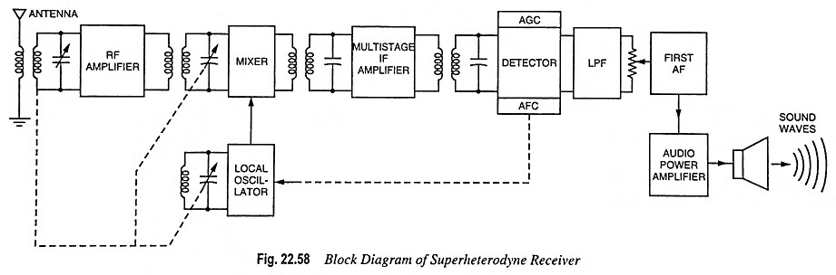
This stage acts to boost the weak signal level from the antenna above the noise level to give some signal selectivity and to avoid reradiation of the local oscillator signal.
The output signal from the RF amplifier is fed to one input of the mixer circuit and the local oscillator signal to the other. While separate circuits may be used for the mixer and oscillator, the two functions are frequently combined in the same circuit. The oscillator is also variably tuned so as to track the incoming signal frequencies. In some receivers (especially older ones) the variable tuning is done with a multigang variable capacitor especially cut to give proper frequency tracking. Newer receivers mostly make use of varactor diode tuning, which allows remote control and very compact circuits.
The mixer output is fed to two cascaded tuned IF amplifiers which are fixed-tune and provided with sufficient selectivity to reject adjacent channel signals. Older receivers typically used tuned transformers for the filtering action, but many recent receivers use inexpensive ceramic resonator filters with a high-gain IC amplifier.
The output from the IF amplifier chain is fed to the detector (or demodulator) to retrieve the modulating signal. Usually, diode detector circuit is employed as it causes low distortion and provides excellent audio-fidelity. The detector also provides signals for automatic gain control (AGC) and for automatic frequency control (AFC) in FM receivers. The AGC signal is used as a bias signal for reducing the gain of the RF and the IF amplifiers to avoid detector overload on strong signals. The AFC signal is used to adjust the frequency of the local oscillator so that it “locks” to the average of the received signal frequency and to counteract minor mistuning problems.
The audio signal from the detector (or demodulator) is passed through a low-pass filter (LPF) for removal of unwanted high frequency components and then through a volume control to an audio amplifier (AF). The AF is usually one low level audio stage followed by a power amplifier and a speaker, which converts the audio signal into sound waves corresponding to the original sound at the broadcasting station.
The superheterodyne receiver has the following advantages:
- Large Amplification: The amplification is carried out at intermediate frequency which is much lower than radio frequency, so the signal can be amplified to a higher level (RF amplification at low frequencies is more stable because of reduced feedback via stray and interelectrode capacitance).
- Improved Selectivity: The selectivity is the characteristic of the receiver that determines the extent to which the receiver is capable of distinguishing between the desired signal and the signals of other frequencies. The quality factor Q of the tuned circuit, because of smaller losses at intermediate frequency, is improved and, therefore, the amplifier circuits operate with maximum selectivity.
- Smaller Cost: The superheterodyne receiver is cheaper than straight radio receiver because in superheterodyne receiver fixed RF amplifiers are used.
3. FM Receiver: FM receivers invariably make use of superheterodyne configuration, and the basic block diagram is the same as that for an AM receiver. However, the antenna, RF amplifier and local oscillator usually operate in the VHF of 88-108 MHz and have an intermediate frequency (IF) of 10.7 MHz with a bandpass of 2 x 75 kHz i.e., 150 kHz.
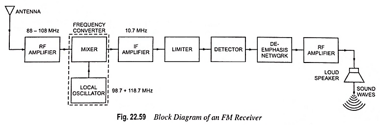
In both AM and FM receivers, the purpose of stage following the IF amplifier is to extract the information from the carrier signal. Since the information was originally impressed on the carrier by modulating its frequency, the FM detector must sense frequency—not amplitude-variations. Thus, basic differences between FM and AM receiver lie in the detector (or demodulator) circuit. Also, since FM signals may occupy a wider band for given modulating signal, the RF and IF bandwidths are typically greater. Since FM is usually confined to higher frequencies, this wider bandwidth need is more tolerable.
The audio portion of an FM receiver is identical to that for an AM receiver, except that the audio portion of an FM broadcast receiver is usually capable of amplifying without distortion a wider frequency range than an AM broadcast receiver-typically 15 kHz versus 5 kHz.
The functions of components other than limiter and de-emphasis network are the same as explained in case of superheterodyne receiver. In FM receiver limiter is provided to remove all amplitude variations, caused by noise from IF signal which might have crept into the FM signal. The de-emphasis network is provided to reduce the amplitude of high frequencies in the audio signal which was earlier increased at the transmitting station.