Radio Frequency Modulation:
Radio Frequency Modulation – The simplest method of measuring frequency deviation utilises an FM receiver with a BFO as the measuring instrument. The only coupling used is the air waves between the transmitting and receiving antenna, as shown in Fig. 16.16.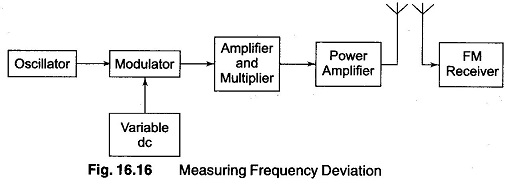
In this setup, the modulating signal is replaced by a variable dc voltage. Since the amplitude of the modulating signal determines the degree of deviation, the frequency is of no importance. The FM receiver is tuned to a frequency corresponding to either the minimum or maximum allowable excursion (swing). The dc voltage is then applied and slowly increased until a zero beat is obtained in the receiver. The amplitude of the dc voltage is now equal to the maximum allowable peak amplitude of the modulating signal.
(Since transmission of a carrier during tuning and testing operations is an undesirable practice, a dummy antenna should be replaced by a regular antenna.) This reduces the output to too low a value for proper reception, a pickup loop may be used to replace the receiving antenna. A suitable signal can then be obtained by loosely coupling the output of the power amplifier to the pickup loop.
Once the degree of deviation has been determined, the modulation index can be calculated by using the equation where
where
- fd = frequency deviation
- fm = frequency of the modulating signal