Successive Approximation Type DVM:
The Successive Approximation Type DVM principle can be easily understood using a simple example; the determination of the weight of an object. By using a balance and placing the object on one side and an approximate weight on the other side, the weight of the object is determined.
If the weight placed is more than the unknown weight, the weight is removed and another weight of smaller value is placed and again the measurement is performed. Now if it is found that the weight placed is less than that of the object, another weight of smaller value is added to the weight already present, and the measurement is performed. If it is found to be greater than the unknown weight the added weight is removed and another weight of smaller value is added. In this manner by adding and removing the appropriate weight, the weight of the unknown object is determined.
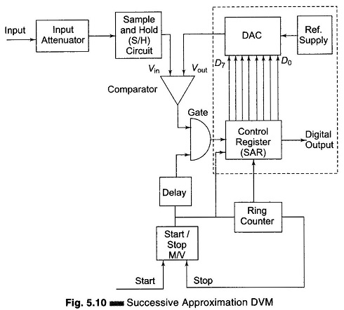
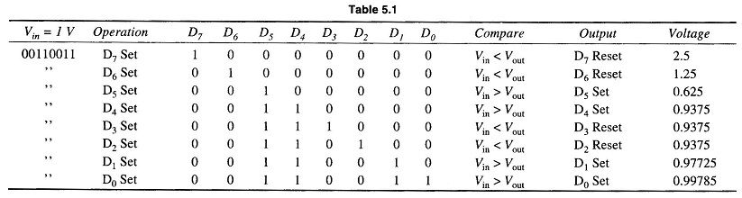
The Successive Approximation Type DVM works on the same principle. Its basic block diagram is shown in Fig. 5.10. When the start pulse signal activates the control circuit, the successive approximation register (SAR) is cleared. The output of the SAR is 00000000. Vout of the D/A converter is 0. Now, if Vin > Vout the comparator output is positive. During the first clock pulse, the control circuit sets the D7 to 1, and Vout jumps to the half reference voltage. The SAR output is 10000000. If Vout is greater than Vin, the comparator output is negative and the control circuit resets D7. However, if Vin is greater than Vout, the comparator output is positive and the control circuits keep D7 set. Similarly the rest of the bits beginning from D7 to D0 are set and tested. Therefore, the measurement is completed in 8 clock pulses.
At the beginning of the measurement cycle, a start pulse is applied to the start-stop multivibrator. This sets a 1 in the MSB of the control register and a 0 in all bits (assuming an 8-bit control) its reading would be 10000000. This initial setting of the register causes the output of the D/A converter to be half the reference voltage, i.e. 1/2 V. This converter output is compared to the unknown input by the comparator. If the input voltage is greater than the converter reference voltage, the comparator output produces an output that causes the control register to retain the 1 setting in its MSB and the converter continues to supply its reference output voltage of 1/2 Vref.
The ring counter then advances one count, shifting a 1 in the second MSB of the control register and its reading becomes 11000000. This causes the D/A converter to increase its reference output by 1 increment to 1/4 V, i.e. 1/2 V + 1/4 V, and again it is compared with the unknown input. If in this case the total reference voltage exceeds the unknown voltage, the comparator produces an output that causes the control register to reset its second MSB to 0. The converter output then returns to its previous value of 1/2 V and awaits another input from the SAR. When the ring counter advances by 1, the third MSB is set to 1 and the converter output rises by the next increment of 1/2 V + 1/8 V. The measurement cycle thus proceeds through a series of Successive Approximation Type DVM. Finally, when the ring counter reaches its final count, the measurement cycle stops and the digital output of the control register represents the final approximation of the unknown input voltage.