2 Phase 4 Pole Permanent Magnet Stepper Motor:
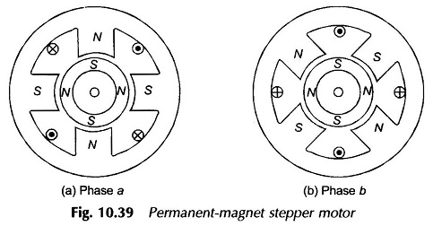
Figure 10.39 shows the phases (stacks) of a 2 Phase 4 Pole Permanent Magnet Stepper Motor. The rotor is made of ferrite or rare-earth material which is permanently magnetized. The stator stack of phase b is staggered from that of phase a by an angle of 90° elect. When the phase a is excited, the rotor is aligned as shown in Fig. 10.39(a). If now the phase b is also excited, the effective stator poles shift counter-clockwise by 22 1/2 ° [Fig. 10.39(b)] causing the rotor to move accordingly. If the phase ‘a’ is now de-energized (with b still energized), the rotor will move another step of 22 1/2 ° . The reversal of phase a winding current will produce a further forward movement of 22 1/2 ° and so on. It is easy to visualize as to how the direction of movement can be reversed.
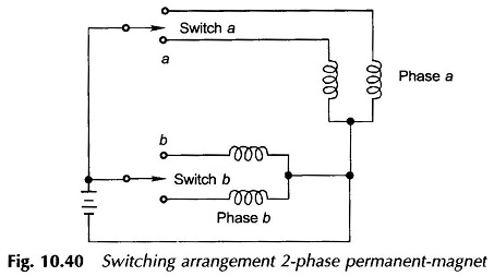
To simplify the switching arrangement, which is accomplished electronically, double coils are provided for each phase. The schematic diagram of switching circuit of 2 Phase 4 Pole Permanent Magnet Stepper Motor is shown in Fig. 10.40.
Application:
Compared to variable-reluctance motors, typical permanent-magnet stepper motors operate at larger steps up to 90°, and at maximum response rates of 300 pps.