Drive Circuits for Stepper Motor:
A Drive Circuits for Stepper Motor is usually driven from a low voltage dc source. When a phase is to be energised, the dc source is connected to the phase by a semiconductor switch S (Fig. 8.9).
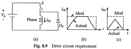
The phase current builds up at the rate decided by the phase winding’s electrical time constant. When the phase is to be de-energised, switch is turned off, which transfers the current to freewheeling diode DF. The current drops to zero, again at the rate decided by the time constant of the phase winding. Motor torque, which is a function of iph, builds up and decays in the same manner. In order to maximize torque capability of a step motor, Drive Circuits for Stepper Motor should be such that the current builds up and decay as fast as possible, ideally as shown by dotted lines in Fig. 8.9(b). This is specially important when high stepping rates are required, as demonstrated in Fig. 8.9(c). The Drive Circuits for Stepper Motor are designed to incorporate this requirement.
Unipolar Drive for Variable Reluctance Motors:
In case of variable reluctance motors, phase currents need only be switched on or off and the current polarity does not matter. Unipolar drive, which is capable of supplying current only in one direction, is sufficient. A simple unipolar drive circuit suitable for low power two phase variable reluctance motor is shown in Fig. 8.10.
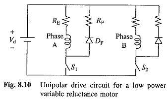
When switch S1 is closed, phase A winding is connected to the dc source Vd and the phase current builds up and when it is opened the phase current decays in the freewheeling path consisting of phase A, DF and RF. The external resistor RE reduces the electrical time constant, thereby speeding up the current build-up. Value of external resistor RE is chosen to fix the value of the electrical time constant and then the source voltage Vd is chosen to produce the rated current IR in the phase winding. Thus
![]()
where RP is the phase winding resistance.
During on period of the switch, phase current also flows through the external resistor RE, causing major proportion of the energy drawn from the source to be dissipated in RE. Further, energy stored in the phase winding inductance during the on period of the switch is all dissipated in free-wheeling circuit resistances when the switch is turned off. Because of these energy losses, the unipolar circuit of Fig. 8.10 is highly inefficient, and therefore, is suitable only for low power Drive Circuits for Stepper Motor.
An efficient unipolar drive circuit capable of providing fast current build-up and decay is shown in Fig. 8.11. It uses chopper principle. Circuit shown is only for one phase. Each other phase will employ a similar circuit. The dc source voltage can now be much larger than in the Drive Circuits for Stepper Motor of Fig. 8.10.
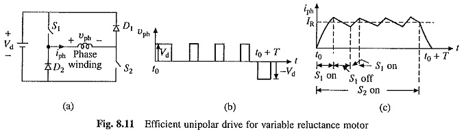
Figures 8.11(a) (b) and (c) show drive circuit, phase voltage and current waveforms respectively. To energise the phase, semiconductor switches S1 and S2 are closed at t = to. This connects phase winding to the dc source voltage Vd and phase current iph builds up fast. When it crosses the rated current IR by a prescribed amount, S1 is switched off. The phase current freewheels through S2 and D2 and decreases below IR. After a fixed interval, S1 is turned on. Phase current iph increases. When it exceeds the rated current IR by the prescribed amount, again S1 is turned off. Thus, alternately turning the switch S1 on an off, the phase current value is maintained to be nearly IR. At t = t0 + T, the phase is de-energised by turning off both S1 and S2. Phase current now flows through the path consisting of D1, source Vd and D2 and major proportion of energy stored in the phase winding inductance is fed back to the source Vd. Since, phase current has to flow against a large voltage Vd, it decays fast to zero.
Bipolar Drive for Permanent Magnet and Hybrid Motors:
A simple bipolar drive circuit for one phase is shown in Fig. 8.12. Each other phase will employ a similar circuit. The phase winding carries a positive current when semiconductor switches S1 and S2 conduct and it carries a negative current when S3 and S4 conduct.
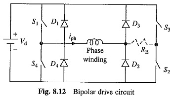
The phase winding is energised with a positive current when S1 and S2 are turned on. The external resistance RE reduces the electrical time constant allowing rapid build-up of phase current. Vd and RE are chosen to satisfy Eq. (8.1). The phase is de-energised by turning off S1 and S2. Winding current now flows through the path consisting of D3, source Vd and D4. The major proportion of energy stored in phase winding inductance is fed back to the source and phase current decays rapidly to zero. Due to the presence of external resistance RE, the drive circuit is inefficient, although it is more efficient than the unipolar drive circuit of Fig. 8.10.
By eliminating RE, and using the chopper principle, an efficient bipolar drive circuit is obtained. The circuit is then operated as follows.
To energise the phase winding with a positive current, S1 and S2 are turned on. The phase current builds up rapidly. When it exceeds the rated current by a prescribed amount (Figs. 8.11 (b) and (c)), S1 is turned off. The phase current freewheels through S2 and D4. After a fixed interval, S1 is turned on again. Thus, phase current fluctuates around the rated value IR. When phase is to be de-energised, both S1 and S2 are turned off. Winding current flows through the path consisting of D3, source Vd and D4. Phase current decays rapidly and energy stored in the winding inductance is recovered by the supply.