Dot Convention in Coupled Circuits:
Dot Convention in Coupled Circuits is used to establish the choice of correct sign for the mutually induced voltages in coupled circuits.
Circular dot marks and/or special symbols are placed at one end of each of two coils which are mutually coupled to simplify the diagrammatic representation of the windings around its core.
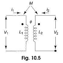
Let us consider Fig. 10.5, which shows a pair of linear, time invariant, coupled inductors with self inductances L1 and L2 and a mutual inductance M. If these inductions form a portion of a network, currents i1 and i2 are shown, each arbitrarily assumed entering at the dotted terminals, and voltages υ1 and υ2 are developed across the inductors. The voltage across L1 is, thus composed of two parts and is given by
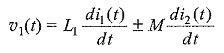
The first term on the RHS of the above equation is the self induced voltage due to i1, and the second term represents the mutually induced voltage due to i2.
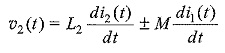
Similarly,
Although the self-induced voltages are designated with positive sign, mutually induced voltages can be either positive or negative depending on the direction of the winding of the coil and can be decided by the presence of the dots placed at one end of each of the two coils. The convention is as follows.
If two terminals belonging to different coils in a coupled circuit are marked identically with dots then for the same direction of current relative to like terminals, the magnetic flux of self and mutual induction in each coil add together. The physical basis of the Dot Convention in Coupled Circuits can be verified by examining Fig. 10.6. Two coils ab and cd are shown wound on a common iron core.
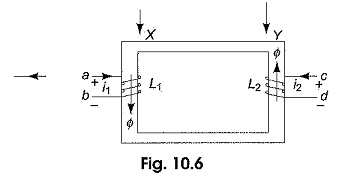
It is evident from Fig.10.6 that the direction of the winding of the coil ab is clock-wise around the core as viewed at X, and that of cd is anti-clockwise as viewed at Y. Let the direction of current ii in the first coil be from a to b, and increasing with time. The flux produced by i1 in the core has a direction which may be found by right hand rule, and which is downwards in the left limb of the core. The flux also increases with time in the direction shown at X. Now suppose that the current i2 in the second coil is from c to d, and increasing with time.
The application of the right hand rule indicates that the flux produced by i2 in the core has an upward direction in the right limb of the core. The flux also increases with time in the direction shown at Y. The assumed currents i1 and i2 produce flux in the core that are additive. The terminals a and c of the two coils attain similar polarities simultaneously. The two simultaneously positive terminals are identified by two dots by the side of the terminals as shown in Fig. 10.7.
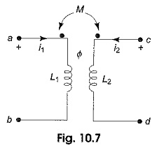
The other possible location of the dots is the other ends of the coil to get additive fluxes in the core, i.e. at b and d. It can be concluded that the mutually induced voltage is positive when currents i1 and i2 both enter (or leave) the windings by the dotted terminals. If the current in one winding enters at the dot-marked terminals and the current in the other winding leaves at the dot-marked terminal, the voltages due to self and mutual induction in any coil have opposite signs.