Inductively Coupled Circuits:
Inductively coupled multi-mesh circuits can be analysed using Kirchhoff s laws and by loop current methods.
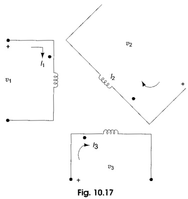
Consider Fig. 10.17, where three coils are inductively coupled. For such a system of inductors we can define a inductance matrix L as
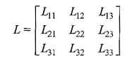
where L11, L22 and L33 are self inductances of the coupled circuits, and L12 = L21; L23 = L32 and L13 = L31 are mutual inductances. More precisely, L12 is the mutual inductance between coils 1 and 2, L13 is the mutual inductance between coils 1 and 3, and L23 is the mutual inductance between coils 2 and 3.
The inductance matrix has its order equal to the number of inductors and is symmetric. In terms of voltages across the coils, we have a voltage vector related to i by
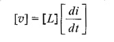
where υ and i are the vectors of the branch voltages and currents, respectively. Thus, the branch volt-ampere relationships of the three inductors are given by
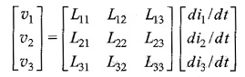
Using KVL and KCL, the effective inductances can be calculated. The polarity for the inductances can be determined by using passivity criteria, whereas the signs of the mutual inductances can be determined by using the dot convention.