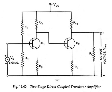
Direct Coupled Transistor Amplifier – Operations and Equivalent Circuit:
Direct coupling is essential for very low frequency (below 10 Hz) applications such as photoelectric current, thermocouple current etc. Thermocouples are used for measurement of temperature in furnaces. The voltage induced in the thermocouple is very small in magnitude (of the order of μV). This voltage is required to be amplified to a suitable level so as to give noticeable deflection on the meter. The furnace temperature may change very slowly and, therefore, the meter should respond to such slow variations. For such applications, direct coupling is the only solution. For low frequency applications, coupling capacitors and bypass capacitors cannot be used. At low frequency coupling capacitors cause significant drop of signal across them resulting in reduction in gain. Similarly at low frequencies, the reactance of emitter bypass capacitors becomes comparable to emitter resistors and thus, bypassing action of the capacitors is affected. If the coupling and bypass capacitors are to serve their purpose, their values have to be extremely large. Such capacitors are not only very expensive, but also are inconveniently large in size. To avoid this, one stage is directly connected to the next stage without intervening any coupling device. Such a coupling is called the direct coupling and the amplifier using such a coupling is called the direct coupled amplifier. Two-stage direct coupled transistor amplifier is shown in Fig. 16.40.
In a two-stage direct coupled transistor amplifier circuit, the noteworthy point is that no coupling and bypass capacitors are used. For such an arrangement the dc levels of one stage are obviously related to the dc levels of the other stages. For this reason the biasing arrangement is required to be designed for the entire network rather than for each stage independently.
Operation of Direct Coupled Transistor Amplifier:
The weak signal is applied to the base of the transistor. Due to transistor action, an amplified output is obtained across the collector load Rc1 of the first transistor. The amplified signal developed across Rc1 is supplied to the base of next transistor. This is further amplified by the next stage and so on. Thus the weak signal is amplified by a direct coupled amplifier.
Circuit Analysis:
The ac equivalent circuit of the direct coupled transistor amplifier given in Fig. 16.40 is shown in Fig. 16.41.
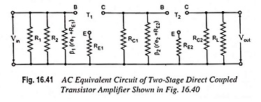
Voltage gain of first stage,
![]()
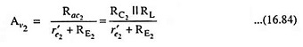
Voltage gain of second stage,
Overall voltage gain,
![]()
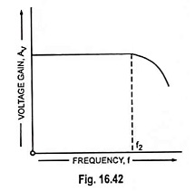
Frequency Response:
It has no coupling and bypass capacitor to cause a drop at low frequencies. The frequency response curve is flat up to upper cutoff frequency f2 which is determined by stray wiring capacitance and internal transistor capacitances. Above this, the gain decreases due to interelectrode capacitance of device and wiring capacitance.
Merits:
- Simple circuit arrangement and very cheap in cost because of use of minimum number of resistors and absence of expensive coupling devices.
- It has the outstanding ability to amplify very low frequency signals (including direct current ones).
- Flat frequency response curve up to upper cutoff frequency, as shown in Fig. 16.42.
Demerits:
- It is not suitable for amplification of high frequency signals.
- It has a poor temperature stability. The transistor parameters, such as β and VBE, vary with the temperature. This causes the collector current and voltage to change. Because of direct coupling, any variation in dc level in one stage is transmitted on an amplified basis to the other stages. Thus the quiescent point is shifted. However, stability is improved to some extent by use of resistor in the emitter circuit, as shown in 16.40.