Coupled Circuits Definition:
Two circuits are said to be ‘coupled’ when energy transfer takes place from one circuit to the other when one of the circuits is energized. There are many types of Coupled Circuits like conductive coupling as shown by the potential divider in Fig. 10.1(a), inductive or magnetic coupling as shown by a two winding transformer in Fig. 10.1(b) or conductive and inductive coupling as shown by an auto transformer in Fig. 10.1(c).
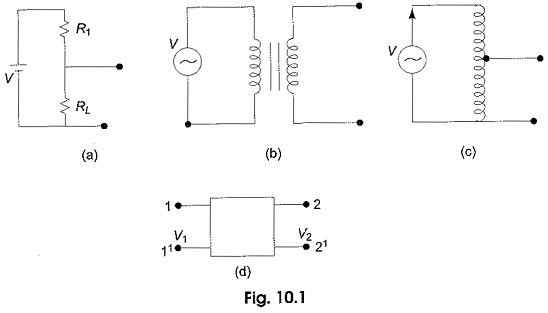
A majority of the electrical circuits in practice are conductively or electromagnetically coupled. Certain coupled elements are frequently used in network analysis and synthesis. Transformer, transistor and electronic pots, etc. are some among these circuits. Each of these elements may be represented as a two port network as shown in Fig. 10.1(d).
Conductivity Coupled Circuit and Mutual Impedance:
A conductively Coupled Circuits which does not involve magnetic coupling is shown in Fig. 10.2(a).
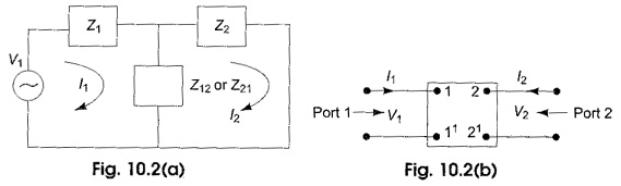
In the circuit shown the impedance Z12 or Z21 common to loop 1 and loop 2 is called mutual impedance. It may consists of a pure resistance, a pure inductance, a pure capacitance or a combination of any of these elements.
The general definition of mutual impedance is explained with the help of Fig. 10.2 (b).
The network in the box may be of any configuration of circuit elements with two ports having two pairs of terminals 1-1′ and 2-2′ available for measurement. The mutual impedance between port 1 and 2 can be measured at 1-1′ or 2-2′. If it is measured at 2-2′.
It can be defined as the voltage developed (V2) at 2-2′ per unit current (I1) at port 1-1′. If the box contains linear bilateral elements, then the mutual impedance measured at 2-2′ is same as the impedance measured at 1 -1′ and is defined as the voltage developed ( V1) at 1-1′ per unit current (I2) at port 2-2′.