Double Tuned Amplifier – Circuit Diagram and Operation:
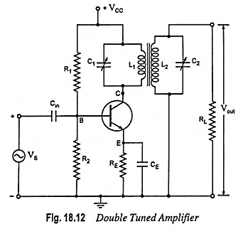
The problem of potential instability with a single tuned amplifier is overcome in a double tuned amplifier which consists of inductively coupled two tuned circuits—one (L1, C1) in the collector circuit and the other (L2, C2) in the output circuit, as shown in Fig. 18.12.
A change in the coupling of the two tuned circuits results in change in the shape of the frequency response curve. By proper adjustment of the coupling between the two coils of the two tuned circuits, the required results (high selectivity, high voltage gain and required bandwidth) may be obtained.
Circuit Operation:
The high frequency signal to be amplified is applied to the input terminal of the amplifier. The resonant frequency of tuned circuit connected in the collector circuit is made equal to signal frequency by varying the value of C1. Now the tuned circuit L1-C1 offers very high impedance to the signal frequency and therefore, large output is developed across it. The output from this tuned circuit (L1-C1) is transferred to the second tuned circuit (L2-C2) through mutual induction. The frequency response of a double tuned amplifier circuit depends upon the magnetic coupling of L1 and L2.
Frequency Response Curve:
The frequency response curves of a double tuned amplifier for different coefficients of coupling are shown in Fig. 18.13. Because of coupling of coils L1 and L2, a portion of load resistance is coupled into the tank circuit L1-C1 and affects it in exactly the same manner as though a resistor had been inserted in series with the coil L1.
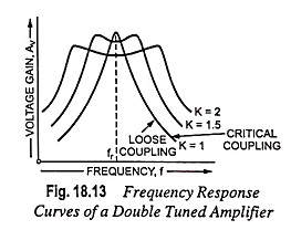
When the coils L1 and L2 are spaced apart, flux created by coil L1 will not link the secondary coil, and these coils will be said to be loosely coupled and under such conditions the resistance reflected from the load (or tuned circuit L2-C2) will be small. Thus the resonance curve will be sharp with high value of Q, as shown in Fig. 18.13. When the two coils L1 and L2 are placed very close together, they are said to be tightly coupled. Under such conditions, the reflected resistance will be larger and consequently Q will be smaller.
From Fig. 18.13 it is obvious that bandwidth increases with the increase in degree of coupling. Naturally, the determining factor in a double tuned amplifier circuit is the coupling, not the Q factor. For a given frequency, the tighter the coupling, the greater is the bandwidth.
It is to be noted that the most suitable response curve is when optimum coefficient of coupling exists between the two tuned circuits. The circuit is then highly selective and also provides sufficient amount of gain for a particular band of frequencies.