Class AB Push Pull Amplifier – Circuit Diagram, Operation and Drawbacks:
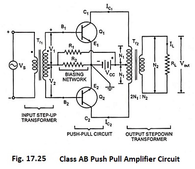
The basic circuit of class AB push-pull amplifier is the same as that of class A push-pull amplifier shown in Fig. 17.25 except that the voltage drop across resistor R2 is so adjusted that it is approximately equal to cutin voltage (0.5 V for Si and 0.1 V for Ge).
Now operation becomes AB type i.e., the collector current flows for more than half the cycle of the input signal but less than the complete cycle. The distortion introduced in this amplifier circuit is less than that in class B push-pull amplifier but more than in class A push-pull amplifier.
The drawbacks of class AB push-pull amplifiers in comparison to class B push-pull amplifiers are lower conversion efficiency and wastage of standby power.