Phase Splitter Circuit for Push Pull Power Amplifiers (or Phase Inverter):
In a push-pull amplifier circuit an input transformer is used to provide the polarity inversion between the two input signals to the push-pull circuit, but the transformer is quite expensive and bulky. The same result may be achieved by using a circuit called the phase splitter or phase invertor. Such a circuit is shown in Fig. 17.29.
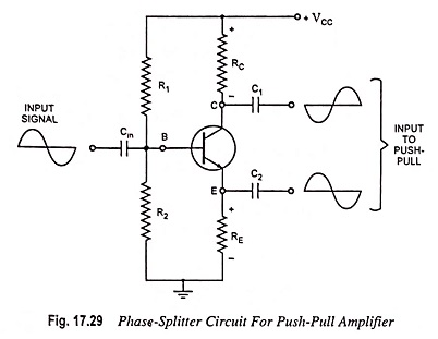
The signal appearing at the collector is of polarity opposite to that of the input signal. During positive half cycle of input voltage, base current, and therefore, collector current increases causing increase in IcRC drop and consequently decrease in collector-emitter voltage Vce. Thus we get negative half cycle of Vce i.e., phase of signal at collector of a CE transistor is reversed. The output from the emitter is of the same polarity as the input. Thus the two output signals obtained from this circuit are of opposite polarity.
Values of resistors RC, RE and β are chosen so as to make the voltage gain for the output signal at collector to be unity. The gain for signal at emitter is 1. Thus the Phase Splitter Circuit provides two signals of equal magnitude but of opposite polarities. The use of input transformer can thus be eliminated.
However, the circuit explained above has three shortcomings as
- Since this circuit is of the emitter-follower type, there is no voltage gain.
- Since the emitter and collector currents are not equal, the output voltages will have some imbalance.
- This Phase Splitter Circuit could not be used to drive a class B push-pull amplifier because output voltages are only equal if driving a resistive load over the entire cycle.
This circuit can be used on a class A push-pull circuit, where the load is constant on each output.