Single Phase Bridge Inverter:
A serious disadvantage of the half-Bridge Inverter of Fig. 11.46 is that it requires a 3-wire dc supply. This is overcome by the commonly employed Single Phase Bridge Inverter circuit of Fig. 11.48(a) which needs four thyristors and four free-wheeling diodes.
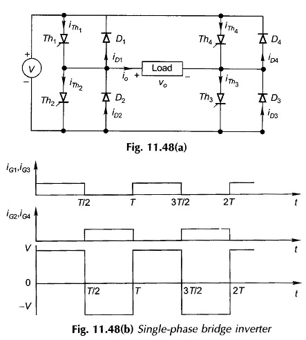
The sequence of thyristor gating and the output waveforms are shown in Fig. 11.48(b). Thyristors Th1 and Th3 must be gated simultaneously at frequency f = 1/T and Th2 and Th4 must be gated 180° out of phase with these.