Current Source Inverter Control of Induction Motor:
A thyristor Current Source Inverter Control of Induction Motor (CSI) is shown in Fig. 6.45. Diodes D1-D6 and capacitors C1-C6 provide commutation of thyristors T1-T6, which are fired with a phase difference of 60° in sequence of their numbers. It also shows the nature of output current waveforms. Inverter behaves as a current source due to the presence of large inductance Ld in dc link.
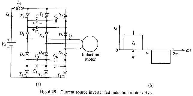
The fundamental component of motor phase current from Fig. 6.45(b) is
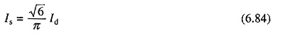
For a given speed, torque is controlled by varying dc link current Id by changing the value of Vd. Therefore, when supply is ac, a controlled rectifier is connected between the supply and inverter and when supply is dc, a chopper is interposed between the supply and inverter (Fig. 6.46). The maximum value of dc output voltage of fully-controlled rectifier and chopper are chosen so that the motor terminal voltage saturates at rated value.
The major advantage of Current Source Inverter Control of Induction Motor is its reliability. In case of VSI (Fig. 6.37(a)), a commutation failure will cause two devices in the same leg (e.g. Tr1 and Tr4) to conduct. This connects conducting devices directly across the source. Consequently, current through devices suddenly rises to dangerous values. Expensive high speed semiconductor fuses are required to protect the devices. In case of Current Source Inverter Control of Induction Motor, conduction of two devices in the same leg does not lead to sudden rise of current through them due to the presence of a large inductance Ld. This allows time for commutation to take place and normal operation to get restored in subsequent cycles. Further, less expensive HRC fuses are good enough for protection of thyristors.
As seen in Fig. 6.45, motor current rise and fall are very fast. Such a fast rise and fall of current through the leakage inductance of the motor produces large voltage spikes. Therefore, a motor with low leakage inductance is used. Even then voltage spikes have large value. The commutation capacitors C1-C6 reduce the voltage spikes by reducing the rate of rise and fall of current. Large value of capacitors is required to sufficiently reduce the voltage spikes. Large commutation capacitors have the advantages that cheap converter grade thyristors can be used but then they reduce the frequency range of the inverter, and therefore, speed range of the drive. Further, due to large values of inductor Ld and capacitors, the Current Source Inverter Control of Induction Motor drive is expensive and has more weight and volume.
Regenerative Braking and Multiquadrant Operation:
When inverter frequency is reduced to make synchronous speed less than motor speed, machine works as a generator. Power flows from machine to dc link and dc link voltage Vd (Fig. 6.46) reverses. If fully-controlled converter of Fig. 6.46(a) is made to work as an inverter, the power supplied to dc link will be transferred to ac supply and regenerative braking will take place, Thus, no additional equipment is required for regenerative braking of CSI drive of Fig. 6.46(a). Change of phase sequence of Current Source Inverter Control of Induction Motor will provide motoring and braking operations in the reverse direction.
The drive of Fig. 6.46(b) can have regenerative braking capability and four-quadrant operation if a two quadrant chopper providing current in one direction but voltage in either direction is used.
Closed Loop Speed Control of CSI Drives:
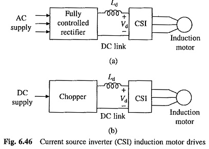
A closed loop Current Source Inverter Control of Induction Motor drive’is shown in Fig. 6.47. Actual speed ωm is compared with the reference speed ω*m. The speed error is processed through a PI controller and slip regulator. The slip regulator sets the slip speed command ω*s1. The synchronous speed obtained by adding ωm ω*s1, determines the inverter frequency. Constant flux operation is obtained when slip speed ωs1 (or rotor frequency) and Is have relationship of Fig. 6.44(b). Since Id is proportional to Is, according to Eqn. (6.84), a relation similar to Fig. 6.44(b) exists between ωs1 and Id for constant flux operation. Based on the value of ω*s1, the flux control block produces a referent current I*d, which through a closed-loop current control adjusts the dc link current Id to maintain a constant flux. The limit imposed on the output of the slip regulator, limits Id at the inverter rating. Therefore, any correction in speed error is carried out at the maximum permissible inverter curent and maximum available torque, giving fast transient response and current protection.
Beyond base speed, machine terminal voltage saturates as explained already. Flux control and closed-loop control of Id are made ineffective. To operate the drive up to rated inverter current, the slip speed limit of the slip regulator must increase linearly with frequency. This is realized by adding to the slip regulator output a signal proportional to frequency.