Microprocessor Control of a Current source Inverter Fed Synchronous Motor:
A drive system employing a Current source Inverter Fed Synchronous Motor has the following features:
- A four quadrant drive can be accomplished very easily.
- A self control, which synchronises the gating pulses of the inverter with rotor position, provides an improved steady-state and dynamic performance.
- The natural commutation using machine voltages is possible in a speed ranging from 10% base speed. At starting and low speeds forced commutation is required, which may be provided by additional commutation circuit of the inverter or by interrupting dc link current.
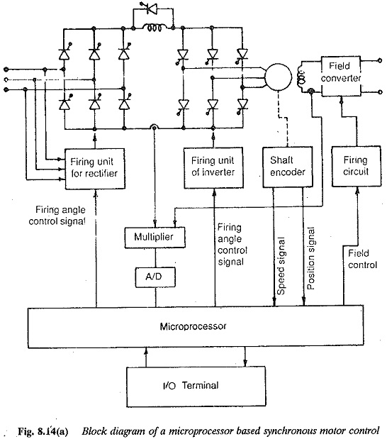
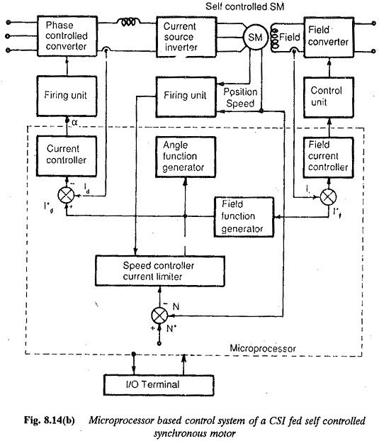
A typical block diagram implementation of a microprocessor for the control of a Current source Inverter Fed Synchronous Motor is shown in Fig. 8.14. The system consists of a dc link converter which is made up of two six pulse bridge converters interconnected by a high smoothing inductance. The dc link inverter feeds a synchronous motor whose field may be controlled by a chopper or a phase controlled rectifier. In the normal operation, the line side converter operates as a rectifier and the machine side one as an inverter. The control pulses to the rectifier are provided by the microprocessor with proper interface between the ac lines and microprocessor, to provide the proper interrupt signal, to synchronise the firing pulses with frequency and to vary the firing angle with respect to the natural firing instant. The Current source Inverter Fed Synchronous Motor is fitted with a shaft encoder. This is an aluminium disc with slots on the periphery (Fig. 8.15) mounted on the shaft. A combination of phototransistor and light emitting diode aligned across the slots provides the necessary train of pulses. These pulses are processed to obtain the rotor position as well as the speed. The forced, commutation is available during starting until the machine accelerates to a speed where natural commutation can take over. The stator and field currents are also sensed and converted to digital form before they are fed to the microprocessor for further processing.
The functions of the microprocessor are now, obvious and can be listed as under:
- The microprocessor should perform the main functions of monitoring and control of the system variables to obtain the desired performance.
- It must be supported by proper software to ensure the necessary commutation of the inverter at low speeds where the machine voltages are not
- It receives the data concerning the system variables, stator and field currents, and processes them to issue the desired control signals to the rectifier and inverter to achieve the desired performance at all operating conditions.
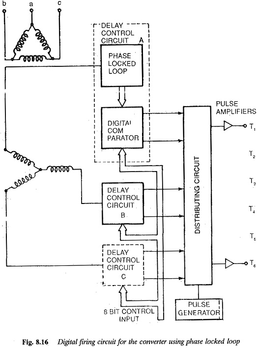
- The link current control is obtained by controlling the firing angle of the line side The firing angle control with proper synchronisation with line voltage and with respect to the natural firing instant may be obtained by implementing the method described above with the control of dual converters. Another scheme using phase locked loop is depicted in Fig. 8.16, the details of which are available in the literature.
- The microprocessor receives the information regarding the rotor position and processes it to control the firing of the inverter.
- It must be software supported and have necessary hardware to accomplish the feedback configurations of the control. It must perform the generation of necessary feedback signals, necessary controllers, limiters and function generators using look-up tables. The controllers must be software oriented so that they can be readily modified
- It processes the information from the rotor position sensor to determine the speed, which is one of the feedback signals.
Starting: It has already been made clear that from zero to about 10% of base speed machine commutation is not effective. To accelerate the rotor to the speed where machine commutation can take over, forced commutation of the inverter thyristors is necessary. This can be achieved by an auxiliary circuit in the inverter with the facility of being cut off when natural commutation takes over. It is also possible by interrupting dc link current with a thyristor across the link inductance. Software programs should be available for the microprocessor to follow the sequence of operations. The second method is described here. On starting the inverter the thyristors are fired in pairs, as the quenching is obtained by making the link current zero. The information must be stored in the address registers. The initial rotor position is decided by the phase reference signals. A pair of thyristors is fired to obtain the maximum torque. At each change of state of the reference signals, commutation is executed by the microprocessor. The thyristor across the link inductance receives the gate signal. Simultaneously the line side converter firing angle is retarded beyond 90° to make it inverter. This changes the polarity of dc link voltage and decreases the link current to zero extremely fast. The current through the thyristor pair also becomes zero. The thyristors switch off. The line side converter is brought back to rectifier mode and the next pair of thyristors of the inverter are fired.
The process is repeated till the Current source Inverter Fed Synchronous Motor accelerates to the desired speed.
- The necessary software to perform the speed regulating and current regulating routines must be provided.
- A typical shaft encoder to provide the rotor position and to control the inverter firing angle must be provided. A typical shaft encoder is discussed separately as it can be used as a generalised hardware for any speed control employing microprocessor.
- During regeneration the firing angle control should be such that the line side converter operates in inverter mode and the machine side one as a rectifier.
Rotor position sensing: A shaft encoder used for the purposes of both rotor position sensing and speed measurement is slightly different from the one discussed under the section speed detection. A typical sensor is explained in the following.
- The shaft encoder used in the control of a Current source Inverter Fed Synchronous Motor is required to provide the triggering pulses to the converter, which are synchronised to the rotor position. The required firing angle delay must also be provided. These pulses must be available to the thyristor during starting employing forced commutation with link current interruption, as well as in the normal operation.
- It is required to provide the information to determine the speed.
- The firing pulses must be such that every 60° one thyristor is fired in The width of the firing pulses may be 120°. The delay angle information to provide the necessary phase difference between the voltage and current must be available.
- To be able to obtain the above information, the shaft encoder must give the necessary phase reference signals and one high frequency signal.
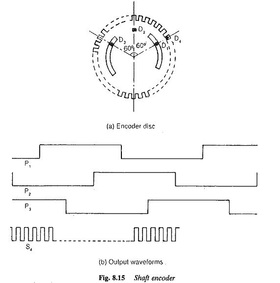
The shaft encoder is a light aluminium disc with a sufficiently large number of slots drilled at the periphery of the disc. The resolution of the firing angle delay depends upon the number of slots. A resolution of 1° may be obtained if there are 360 slots. A high frequency signal is obtained when the disc rotates through an optical sensor. This consists of a light emitting diode aligned with a phototransistor. Whenever a slot comes in between these two the transistor gives out a pulse. A train of pulses is obtained, which can be used as a high frequency signal to determine the firing angle delay as well as speed. The disc also has two more slots, the angle of which depends upon the number of poles, e.g., 90° slots for a four pole machine. Three sensors are placed with a phase shift of 120° electrical so that the sensors produce phase reference signals.
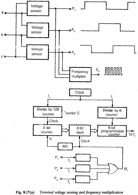
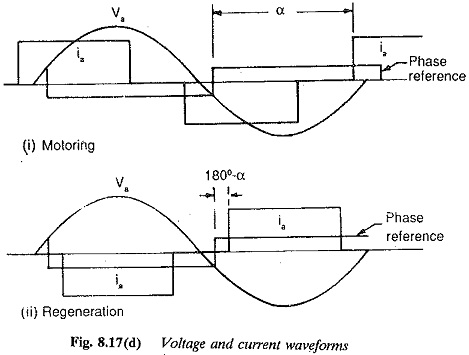
The waveforms of voltage and current during Current source Inverter Fed Synchronous Motor and regeneration are shown in Fig. 8.17. The phase reference signals P1,P2,P3 and the high frequency signal S4 are also shown in the figure. These signals are processed motoring or regeneration is assigned to the first and the remaining delay information is assigned to the remaining seven bits of an eight bit digital word.
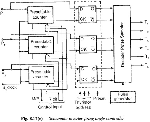
The firing angle controller comprises three delay circuits, a thyristor address register and a pulse distribution circuit (Fig. 8.17). The digital control input is converted to the corresponding delay angle.
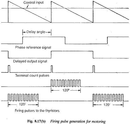
At the beginning of each half cycle of phase reference signal the delay information a is fed into the counter. This is converted to provide the required delay using linear
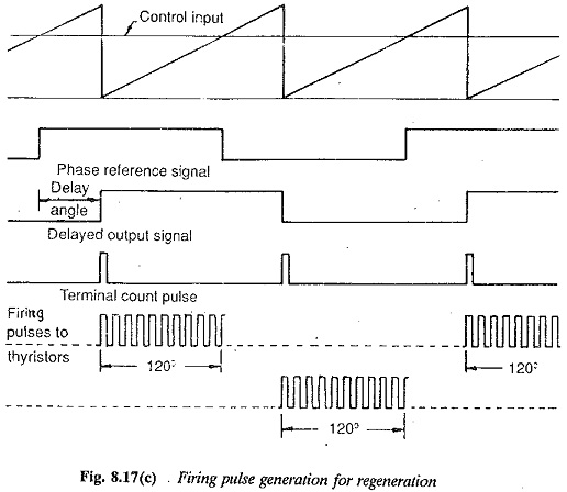
digital ramp techniques. The pulses of the high frequency signal are used to increment or decrement the count. At the terminal count a pulse is generated, which operates as a clock to the D-type flip flops of the thyristor address register. The output signals having a delay of α with respect to phase reference signals are fed to a decoder, where they are combined to produce the modulated firing pulses for all the six thyristors. The pulse trains, shown in Fig. 8.17, are 120° wide and displaced by 60° from each other.
The firing of the inverter must take place during starting also, when there is no machine commutation. The thyristors are actually fired in pairs. For this the delay counters are disabled. The thyristor pairs to be gated are directly addressed by CPU through the thyristor address registers. The phase reference signals are available at the starting of the signals. The appropriate thyristors are fired to provide the torque in the required direction. At the change of state of the phase reference signals, the forced commutation is executed by the microprocessor in the following steps:
1. The thyristor across the link inductor is fired.
2. The line side converter is forced into inverter operation. This reverses the dc link voltage and effectively makes the dc link current zero. The current in the conducting thyristors of the inverter is also zero, making them switch off.
3. The next pair of thyristors of the inverter is fired using the command from the CPU to the thyristor address register. The line side converter is brought back to rectification.
The necessary changes during starting are indicated on the schematic diagram of the firing angle controller. The forced commutation is continued till the Current source Inverter Fed Synchronous Motor accelerates to 10% of speed, where the machine commutation takes over.
The high frequency signal S4 can be used to compute the speed, as described previously, either by counting the number of pulses in a given time or by measuring the time between two pulses. The advantages and disadvantages of these methods have been already described.