Load Commutated Inverter Fed Synchronous Motor Drive:
Load Commutated Inverter Fed Synchronous Motor Drive is shown in Fig. 10.22. The inverter is a current source inverter employing thyristors T1 – T6. The commutation of inverter thyristor is done by the voltages induced in armature of the synchronous motor. A chopper is used to obtain a variable dc voltage Vds from the fixed source voltage V. The Vds is varied with Vdl so that a required current is supplied to the dc link, and therefore, to the motor.
During motoring, the power flows from the dc mains through the chopper, dc link and inverter to the motor. When the inverter firing angle is changed from close to 180° to 0°, the voltage Vdl reverses. If chopper operation is also changed to make Vds negative but less than Vdl in magnitude, the power flows from the load, through the machine, inverter and chopper to the dc mains, giving regenerative braking operation. Here arrangement for dynamic braking is not shown, but it can be incorporated in the same way as shown already.
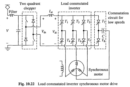
Armature induced voltages are too small to commutate inverter thyristors at low speeds, including standstill. Thyristors T7 and T8 and capacitor C are used to commutate inverter thyristors at low speeds. Around 10% of the base speed gate pulses are withdrawn from T7 and T8, and the load commutation is employed.
Due to the presence of Ld, inverter is essentially current source inverter. Therefore, each traction motor is fed by its own inverter. If there are four traction motors, four such inverters will be required.
Further, because of current source characteristics, the inverters can be connected in series but not in parallel. Thus, when four traction motors are used one alternative will be to connect all four inverters in series fed by a common chopper. Such a series connection will have adverse effect on adhesion. Alternatively, one can connect two inverters in series, and each such series pair is then fed by its own chopper.
This Load Commutated Inverter Fed Synchronous Motor Drive has following features in comparison to PWM VSI induction motor drive:
- Because of an additional power stage (i.e. chopper), the converter efficiency is lower, but the motor efficiency is higher
- Due to the presence of large inductance Ld, the drive has slow dynamic response giving inferior adhesion.
- Larger weight and volume.
- Each motor should have its own inverter and these inverters can be connected in series but not in parallel. When large traction motors are involved the drive becomes expensive and Series connection also has adverse effect on adhesion.
- Inverter is more reliable due to absence of shoot through fault.
- Because of torque pulsations produced by harmonics, the acceleration is not smooth. This also has adverse effect on adhesion.