Voltage Commutated Chopper Circuit:
This Voltage Commutated Chopper Circuit comprises an auxiliary thyristor Th2, a diode D, inductor L and capacitor C as shown in Fig. 11.32 wherein the total chopper circuitry has been outlined with a dotted box.
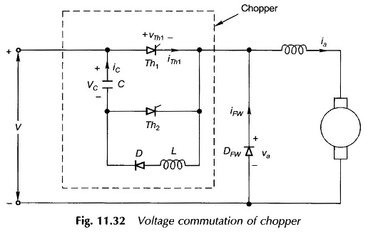
To start the Voltage Commutated Chopper Circuit, capacitor C is initially charged by firing the thyristor Th2; charging is now from the source via C, Th2 and load with the charging thyristor turning off as the charging current decays to zero.
Voltage and current waveforms of a voltage Commutated Chopper are shown in Fig. 11.33. The main thyristor Th1 is triggered at t0. Current flows in two paths—load current ia through Th1 and commutation current iC through C, Th1, L and D. The commutation current iC is oscillatory of frequency determined by the LC series circuit. At the end of the first pulse of iC, C is charged negatively and the diode D blocks-off further flow of current.
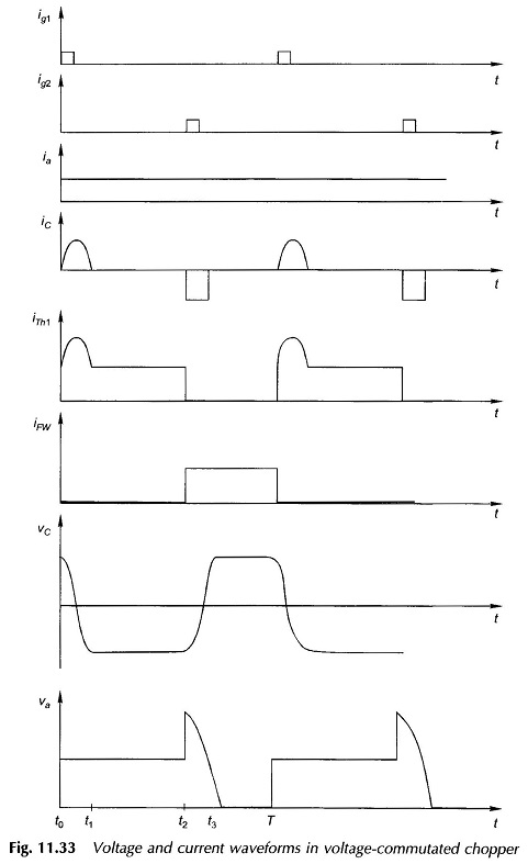
To turn-off the main thyristor Th1, the auxiliary thyristor Th2 is triggered at t2. This causes the fully-charged capacitor C to reverse-bias Th1 and causes it to turn off. The capacitor C itself gets charged positively from the source through Th2 and load; Th2 itself turns off at t3, the end of the charging process when the charging current decays to zero, i.e. it is load-commutated. The load current now freewheels through DFW. At t = T, the main thyristor is again triggered and the cycle repeats.
This simple chopper was extensively used at one time. It suffers from the fact that the capacitor has to be initially charged to begin the operation. Further, the voltage jumps to twice the value as soon as commutation is initiated by triggering Th2.