Step up Chopper – Definition, Circuit Diagram and its Working Principle:
In a step-down chopper the output voltage lies between zero and supply voltage. However, there are techniques by which the output of a chopper obtained is higher than the supply voltage. Such types of choppers are called Step up Chopper. The circuit diagram of a Step up Chopper is shown in Fig. 27.28 (a). In figure, the chopper is represented by a switch S.
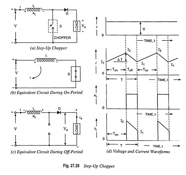
In this chopper, a large inductor in series with the supply voltage source is essential, as shown in Fig. 27.28 (a). When the chopper is on, the current flows through inductance L, chopper S and power supply source, as shown in Fig. 27.28 (b) . During this on-period Ton, the inductor L stores energy.
When the chopper is off, the inductor current is forced to flow through the diode and load for a period Toff because the inductor current cannot die instantaneously. As the current tends to decrease, polarity of the emf induced in the inductor is reversed, as illustrated in Fig. 27.28 (c).
Assuming negligible voltage drop across diode D, the voltage equation for outer loop may be written as

If the rate of fall of current through inductor is di/dt, Eq. (27.39) may be written as
![]()
It means that the inductor voltage adds to the source voltage to force the inductor current into the load. In this manner, the energy stored in inductor is released to load. Here, higher value of inductance L is preferred for getting lesser ripple in the output.
During the time Ton, when when the chopper is on, the energy stored in the inductor is given by

Above Eq. (27.41) is based on the assumption that the variation of output current is linear.
During the period Ton, the current through the inductor rises to peak value I2 while during off period Toff it falls to value I1 and rises again to I2 in the next on state of the chopper. It is shown in Fig. 27.28 (d). Thus, in a cycle the average value of current is given by Ia = I1 + I2/2. Hence the energy stored in the inductor L is given by

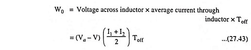
and this energy is released by the inductor to the load during the off-period, Toff . Thus energy released by inductor L during off period is given by
Assuming the system to be lossless, in the steady-state the two energies will be equal i.e.,
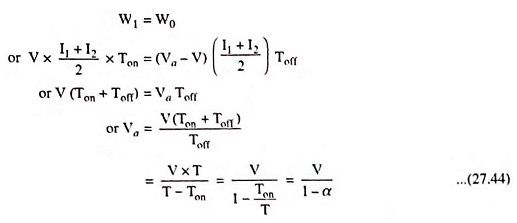
The value of α, the duty cycle lies between zero and unity. Corresponding average values of load voltage Va lies between V and infinity. Thus the output voltage of step up chopper is never less than the supply voltage V i.e., for 0 ≤ α ≤ 1 the output voltage of step up chopper lies in the range V ≤ Va ≤ α.
The step up chopper can be employed for regenerative braking of dc motors even at low operating speeds. Let V represent the motor armature voltage and Va the dc source voltage in Fig. 27.28 (a) .
Regenerative braking takes place when (V + L di/dt) exceeds Va. Even at decreasing motor speeds, duty cycle α can be so adjusted that (V + L di/dt) fixed supply voltage Va.