Oil Pressure Governor and its Working Principle:
The primary purpose of a governor for a hydro electric unit is to control the speed and loading of the unit. It is accomplished by controlling the flow of water through turbine. In Normal conditions the turbine should run at constant speed irrespective to changes in load. This is achieved by means of a governor called oil pressure governor.
The oil pressure governor consisting of following parts namely
- Servomotor (or) Relay cylinder
- Pendulum (or) Actuator
- Distributing valve (or) Control valve
- Oil pump
- Pipes connecting oil pump
(i) Servomotor (or) Relay cylinder
Servomotor consists of a piston which moves due to oil pressure and the movement of piston is controlled by control valve. The piston rod is connected to Turbine Guide mechanism which controls the amount of water entering the turbine.
(ii) Pendulum (or) Actuator
It is a flyball mechanism operated by a sleeve connected to the turbine main shaft.
(iii) Distributing valve (or) Control valve
Distributing valve is housed inside a cylinder with a piston and connecting rod connecting to the rigid fulcrum. And the distributing valve cylinder consists of two ports P and Q which controls the supply of oil to the servomotor.
(iv) Oil pump
The function of an oil pump is to pressurize the oil from the sump and send it to the cylinder of distribution valve.
(v) Pipes connecting to oil sump
The pipes connecting oil sump is connected to distributing valve and the distributing cylinder is connected to servomotor.
Working Principle of Oil Pressure Governor:
When the turbine is running at normal speed, the distributing valve and relay cylinder position remains same in their Normal place as shown in Fig.4.17 the ports P and Q remain closed.
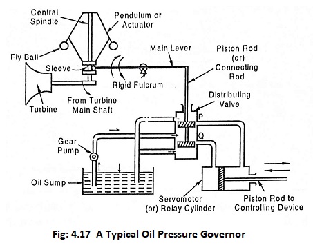
When the load on the turbine increases, the speed of turbine reduces due to this speed of the central spindle reduces which brings the flyball down.
Due to the displacement of flyball, the sleeve will also come down. This causes the main liver to rise and pulling the piston upward of distributing valve. This slight upward movement will open the port “P” and the oil under pressure will move from distributing valve to the servomotor (or) relay cylinder. This causes the piston to move to the left. This movement is transmitted to the turbine guide mechanism (or) controlling device, which causes more water to enter the turbine and hence the turbine will run faster and the speed will begin to increase, therefore speed becomes normal again.
As the speed becomes normal, the piston of distributing valve, the main lever and servomotor will reach their initial position.
Similarly when the load on the turbine decreases, the speed will increase (i.e) vice versa. To bring the speed to normal, the oil pressure governor acts quickly and operates the guide mechanism.
For better understanding of turbine guide mechanism, the guide mechanism of impulse turbine is shown in Fig.4.18.
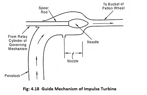
The Fig.4.18 shows that the governor closes the nozzle opening partially by pushing the needle into the nozzle thus allows less water to enter the turbine, therefore the turbine will run slow.