Pressure Inductive Transducer:
Pressure Inductive Transducer – A simple, arrangement, wherein a change in the inductance of a sensing element is produced by a pressure change, is given in Fig. 13.22.
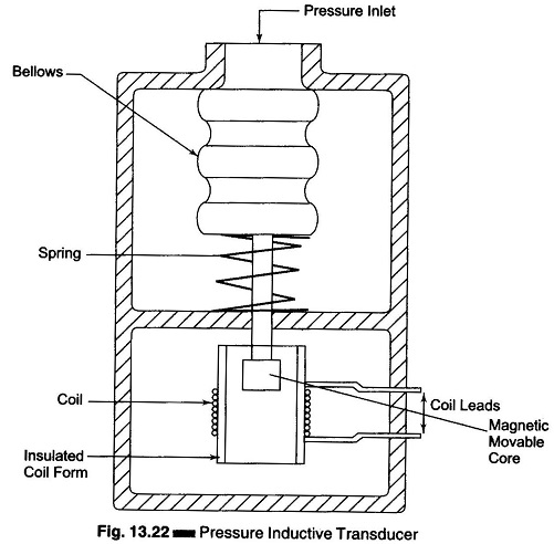
Here the pressure acting on a movable magnetic core causes an increase in the coil inductance corresponding to the acting pressure. The change in inductance can again be made on the basis of an electrical signal, using an ac bridge.
An advantage of the Pressure Inductive Transducer type over the resistive type is that no moving contacts are present, thereby providing continuous resolution of the change, with no extra friction load imposed on the measuring system.
In a slightly modified form, this principle is used to obtain a change in mutual inductance between magnetically coupled coils, rather than in the self inductance of a single coil. When a change in an induced voltage is involved, the transducer is sometimes called a variable reluctance sensor or magnetic pickup. A very important example of the mutual type is the LVDT.
1. Inductive Position Transducers (Synchro’s):
Synchro’s is a generic name for a faculty of Pressure Inductive Transducer devices which can be connected in various ways to form shaft angle measurement. All these devices work essentially on the same principle, that is of a rotating transformer. A Synchro appears like an AC motor consisting of a rotor and a stator.
Synchro’s are normally used in control system, but have properties that can be used in instrumentation also.
A Synchro can be an angular position transducer working on Pressure Inductive Transducer principle, wherein a variable coupling between primary and secondary winding is obtained by changing the relative orientation of the windings.
Internally, most synchro’s are similar in construction. They have a rotor with one or three windings capable of revolving inside a fixed stator. There are two common types of rotors, the salient pole and the wound rotor.
The primary winding is a single phase winding wound on a rotor made of laminations. The connection to the rotor windings are made through precision slip rings shown in Fig. 13.23.
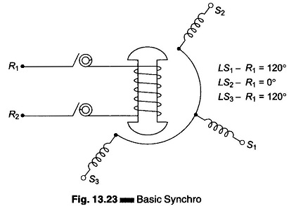
The stator has a 3-phase winding with the windings of the 3-phase displaced by 120°. The synchro may be viewed as a variable coupling transformer. A synchro is also called as Selsyn.
The rotor is energized by an ac voltage and coupling between rotor and stator windings varies as a trigonometric or linear function of the rotor position.
Synchro systems consists of two or more interconnected synchros. They are grouped or connected together according to the purpose to be used.
A Synchro system formed by interconnection of the devices called the Synchro transmitter and Synchro control transmitter is perhaps the most widely used error detector in feedback control system. It measures and compares two angular displacements and its output voltage is approximately linear with angular displacement.
The conventional Synchro transmitter (TX) uses a salient pole rotor with sleeved slot. When an ac excitation voltage is applied to the rotor, the resultant current produces a magnetic field and by transformer action induces voltages in the stator coils. The effective voltage induced in any stator coil depends upon the angular position of the coil axis with respect to the rotor axis (when the coil voltage is known, the induced voltage at any angular displacement can be determined).
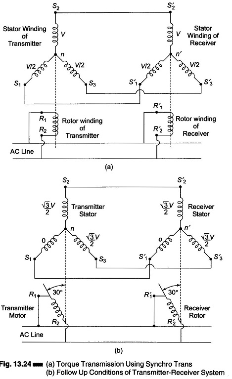
Initially winding S2 of the stator of transmitter is positioned for maximum coupling with the rotor winding as shown in Fig. 13.24(a). Suppose the voltage is V, the coupling between S1 and S2 of the stator and primary (rotor) winding is a cosine function. In general if the rotor is excited by 50 Hz ac, also called reference voltage, the voltage induced in any stator winding will be proportional to the cosine of the angle between the rotor axis and the stator axis. The voltages induced across any pair of stator terminals (S1 – S2, SI – S3, or S2 – S3) will be sum or difference, depending on the phase of the voltage measured across the coils.
For example, if a reference voltage V sin ωt excites the rotor of a synchro (R1 – R2), the stator terminals will have a voltage of the following form:
![]()
where θ is the shaft angle.
These voltages are known as Synchro format voltages.
Therefore, the effective voltages in these windings are proportional to cos 60° or they are V/2 each. So long as the rotors of the transmitter and receiver remains in this position, no current will flow between the stator windings because of the voltage balance.
When the rotor of the transmitter is moved to a new position, the voltage balance is disturbed or changed. Assuming that the rotor of the transmitter is moved through 30° as shown in Fig. 13.24(b), the stator winding voltages of the transmitter will be changed to 0,√3/2 V and √3/2 V respectively.
Hence, a voltage imbalance occurs between the stator windings of the transmitter and receiver. This voltage imbalance between the windings causes current to flow between the windings producing a torque that tends to rotate the rotor of the receiver to a new position where the voltage balance is again restored. This balance is restored only if the receiver turns through the same angle as the transmitter and also the direction of rotation is the same as that of the transmitter. Hence a Synchro can be used to determine the magnitude and direction of angular displacement.
Torque synchros are required if it is necessary to transmit angular displacement information from a shaft of one Synchro to the shaft of another Synchro without using any additional amplifiers or gears.
Torque synchro are commonly connected in repeater system consisting of torque transmitter and torque receiver. These repeater system is accurate to ± 1° and is used in systems in which a rotating devices output is required to position a remote pointer.
Today, most of these units have been replaced by a Syncrho-to-digital converter driving a LED display of the digital readout of angular position.
2. Selsyn:
Synchros also called as Selsyn are motor like devices used to form position sensing and indicating system. Its principle is also based on the variation of mutual coupling between transmitter windings.
There are two types of Selsyn:
- Torque type
- Control type
Torque type of Selsyn consists of two rotors with a single winding and a stator with 3 windings distributed 120° apart. This section acts as a transmitter. The generator stator windings are connected to the other remotely located 3 phase windings. This section acts as a receiver and also has receiver rotor windings. The torque Selsyn is shown in Fig. 13.25.
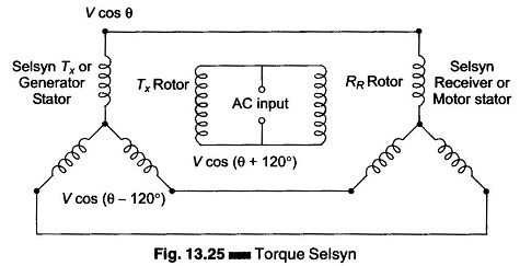
The rotor of both units are excited through slip rings by an ac source at a convenient frequency.
If the receiver rotor is in the same relative position with reference to stator windings as the transmitter, the Pressure Inductive Transducer coupling is identical and no stator current flows between the two units.
If transmitter rotor is shifted from this null position, voltages induced in the two stator will be the difference and a current starts to flow. This current flow produces a torque in the receiver which causes the receiver rotor to move into alignment with the new transmitter rotor position and the previous null position is obtained. Hence the receiver always follow the angular motion in accordance with that of the transmitter. Its accuracy is limited by the friction of the receiver bearings and calibration of its dial face.
3. Control Synchro:
When larger amounts of power or torque and greater accuracy are required control synchros are used.
These devices are used for providing and handling control signals to a servo amplifier when more power and accurate angular displacement of a large load are required. The control synchros are not designed to handle any mechanical load.
The Control Transformer (CT) develops an ac rotor output voltage that is proportional to the relative shaft angles between synchro transmitter and control transformer. The devices are normally connected as shown in Fig. 13.26.
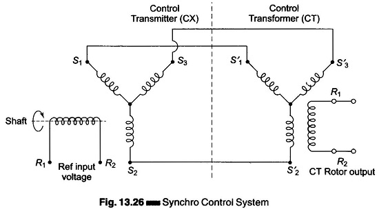
The two most common control synchro are Control Transmitter (CX) and Control Transformer (CT).
The output of the CX (transmitter) is fed to the stator of CT (transformer). The CT is a high impedance version of the torque receiver with its rotor aligned at 90° to that of transmitter (TR).
In a control system, when the shaft angle of the CX equals that of CT shaft angle, a minimum and null voltage will appear on the rotor terminals R1 and R2 of the CT. Any variation from this null will produce a signal in CT rotor whose phase will depend in which direction it is moved off the null.
A simple closed loop servo system using a CX and CT control system is shown in Fig. 13.27.
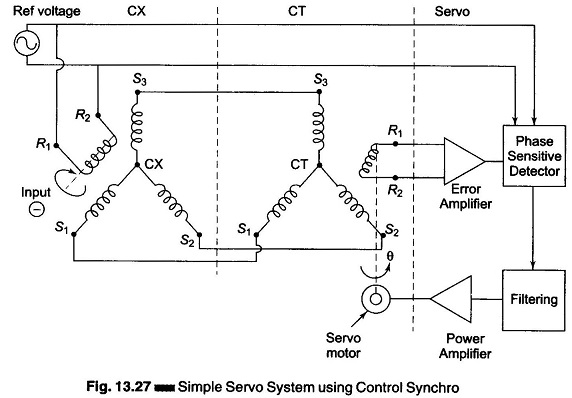
When the shaft of the CX is turned to some angle θ, S1, S2 and S3 output provide synchro format voltage as discussed previously. These voltages are transmitted to the CT stators S1, S2, S3. If the CT is not at the input angle θ, a voltage will be produced at the output of the CT rotor winding. This signal (error) is amplified, phase detected and fed to a servo amplifier to cause a servo motor to position a load and the CT shaft to a position where the CT rotor output is minimum (null). The direction, in which the motor turns towards the angle θ, is determined by the phase of the CT rotor with respect to the reference voltage. Hence servo action takes place.