Differential Instrumentation Amplifier Transducer Bridge:
Figure 14.25 shows a simplified circuit of a Differential Instrumentation Amplifier Transducer Bridge.
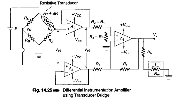
In this circuit a resistive transducer (whose resistance changes as a function of some physical energy) is connected to one arm of the bridge.
Let RT be the resistance of the transducer and ΔR the change in resistance of the resistive transducer. Hence the total resistance of the transducer is (RT ± ΔR).
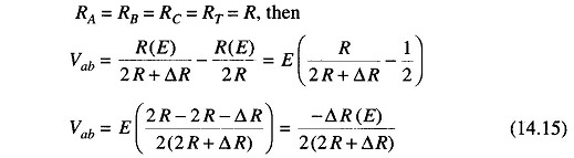
The condition for bridge balance is Vb = Va, i.e. the bridge is balanced when Vb = Va, or when

Therefore,
![]()
The bridge is balanced at a desired reference condition, which depends on the specific value of the physical quantity to be measured. Under this condition, resistors RA, RB and RC are so selected that they are equal in value to the transducer resistance RT. (The value of the physical quantity normally depends on the transducers characteristics, the type of physical quantity to be measured, and the desired applications.)
Initially the bridge is balanced at a desired reference condition. As the physical quantity to be measured changes, the resistance of the transducer also changes, causing the bridge to be unbalanced (Vb ≠ Va). Hence, the output voltage of the bridge is a function of the change in the resistance of the transducer. The expression for the output voltage Vo, in terms of the change in resistance of the transducer is calculated as follows.
Let the change in the resistance of the transducer be ΔR. Since RB and RC are fixed resistors, the voltage Vb is constant, however, the voltage Va changes as a function of the change in the transducers resistance.
Therefore, applying the voltage divider rule we have

The output voltage across the bridge terminal is Vab given by Vab = Va – Vb.
Therefore,
![]()
However, if
The output voltage Vab of the bridge is applied to the Differential Instrumentation Amplifier Transducer Bridge through the voltage followers to eliminate the loading effect of the bridge circuit. The gain of the basic amplifier is (RF/R1) and therefore the output voltage Vo of the circuit is given by
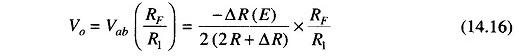
It can be seen from the Eq. (14.16) that Vo is a function of the change in resistance ΔR of the transducer. Since the change is caused by the change in a physical quantity, a meter connected at the output can be calibrated in terms of the units of the physical quantity.
Applications of Instrumentation Amplifier Transducer Bridge:
We shall now consider some important applications of instrumentation amplifiers using resistance types transducers. In these transducers, the resistance of the transducer changes as a function of some physical quantity. Commonly used resistance transducers are thermisistors, photoconductor cells, and strain gauges.
Temperature Indicators Using Thermistor:
The Thermistor is a relative passive type of temperature resistance transducer. They are basically semiconductors.
In many respects, a thermistor resembles a conventional resistor. It is usually a two-terminal device. It has resistance as its fundamental property. It is generally installed and operated in the manner of an ordinary resistor. But its great difference is that it has a negative temperature coefficient (NTC) or positive temperature coefficient (PTC) type. Most thermistors exhibit an NTC characteristic. An NTC type is one in which its resistance decreases with increase in temperature. The temperature coefficient is expressed in ohms/°C.
Since it is a thermally sensitive resistor, it has a high temperature coefficient of resistance and is therefore well suited for temperature measurement and control.
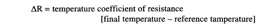
If in the bridge circuit of Fig. 14.25 the transducer used is a thermistor, the circuit can thus be used as a temperature indicator. The output meter is then calibrated in °C or °F. The bridge is balanced initially at a desired reference condition. As the temperature varies, the resistance of the thermistor also changes, unbalancing the bridge, which in turn produces a meter deflection at the output. By selecting the appropriate gain for the Differential Instrumentation Amplifier Transducer Bridge, the meter can be calibrated to read a desired temperature. In this circuit, the meter movement (deflection) depends on the amount of unbalance in the bridge, which is caused by a change in the value of thermistor resistance ΔR. The change ΔR for the thermistor can be determined as follows.
If the meter in this circuit is replaced by a relay, and if the output of the Differential Instrumentation Amplifier Transducer Bridge drives the relay that controls the current in the heat-generating circuit, a temperature controller can be formed. A properly designed circuit should energize a relay when the temperature of the thermistor drops below a desired value, causing the heater unit to turn on.
Light Intensity Meter:
If in the bridge circuit of Fig. 14.25, the transducer is a photocell, this circuit can be used as a light intensity meter. Initially the bridge is balanced for the dark condition, therefore when exposed to light the bridge becomes unbalanced, to a degree depending upon the intensity of light. This unbalance causes the meter to deflect. To measure the change in light intensity, the meter is calibrated in terms of Lux or Lumen.
The light intensity meter can also be designed using a single input inverting or non-inverting opamp, but the light intensity meter using an instrumentation amplifier is more accurate and stable, because the common mode (noise) voltages are effectively cancelled by the differential mode.
Analog Weight Scale:
Figure 14.25 can be converted into a simple analog weight scale by connecting strain gauges in the bridge circuit. These strain gauges are connected in all the four arms of the bridge, as shown in Fig. 14.26. The strain gauge elements are mounted on a base of the specially made weight platform, on which an external force or weight is placed. One pair of strain gauge elements in opposite arms elongates, (i.e. RT1 and RT3 both increases in resistance) while the other pair compresses (RT2 and RT4 both decreases in resistance), and vice-versa.
The bridge is balanced when no external force or weight is applied, i.e. RTI = RT2 = RT3 = RT4 = R, and the output voltage of the weight scale is zero.
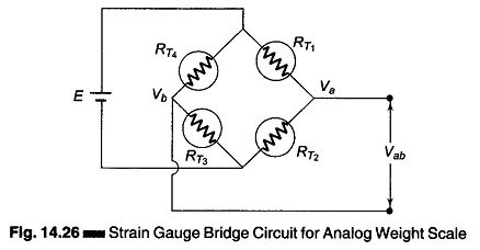
Suppose a weight is placed on the scale platform and RT1 and RT3 increases in resistance. Then RT2 and RT4 decrease in resistance by the same value AR and the bridge is unbalanced, thereby giving an unbalanced output voltage. This unbalanced voltage Vab is given by
![]()
where
- E – excitation voltage of the bridge.
- R = RT1 = RT2= RT3 = RT4 = unstrained gauge resistance
- ΔR – change in gauge resistance.
The Differential Instrumentation Amplifier Transducer Bridge then amplifies the voltage Vab, giving a deflection on the meter movement. As the gain of the amplifier is (+ RF/R1), the output voltage Vo is given by

The gain of the amplifier is selected depending on the sensitivity of the strain gauge and on the full scale deflection requirements of the meter. The meter can be then calibrated in grams or kilograms.
For better accuracy and resolution, a micro based digital weight scale may be constructed. However, such a scale is much more complex and expensive then the analog scale.