Photoelectric Transducer Working Principle:
Photoelectric Transducer can be categorized as photo emissive, photo-conductive or photo-voltaic.
In photo emissive devices, radiation falling on a cathode causes electrons to be emitted from the cathode surface.
In photo conductive devices, the resistance of a material is changed when it is illuminated.
Photo voltaic cells generate an output voltage proportional to the radiation intensity. The incident radiation may be infrared, ultraviolet, gamma rays, X-rays, or visible light.
Photo Multiplier Tube:
The photo multiplier tube consists of an evacuated glass envelope containing a photo cathode, an anode and several additional electrodes, termed Dynodes, each at a higher voltage, than the previous dynode.
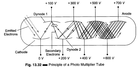
Figure 13.32 illustrates the principle of the photo multiplier. Electrons emitted by the cathode are attracted to the first dynode. Here a phenomenon known as secondary emission takes place.
When electrons moving at a high velocity strike an appropriate material, the material emits a greater number of electrons than it was struck with.
In this device, the high velocity is achieved by the use of a high voltage between the anode and the cathode. The electrons emitted by the first dynode are then attracted to the second dynode, where the same action takes place again. Each dynode is at a higher voltage, in order to achieve the requisite electron velocity each time. Hence, secondary emission, and a resulting electron multiplication, occurs at each step, with an overall increase in electron flow that may be very great. Amplification of the original current by much as 105 – 109 is common. Luminons sensitivities range from 1A per lumen or less, to over 2000 A per lumen. Typical anode current ratings range from a minimum of 100 μA to a maximum of 1 mA.
The extreme luminous sensitivity possible with these devices is such that for a sensitivity of 100 A per lumen, only 10-5 lumen is needed to produce 1 mA of output current.
Magnetic fields affect the photo multiplier because some electrons may be deflected from their normal path between stages and therefore never reach a dynode or anode. Hence, the gain falls. To minimize this effect μ-metal magnetic shields are often placed around the photo multiplier tube.
Photo Conductive Cells or Photo Cells:
The devices discussed above achieve an electrical output by photo emission. Another Photoelectric Transducer effect that is very useful is the photo conductive effect.
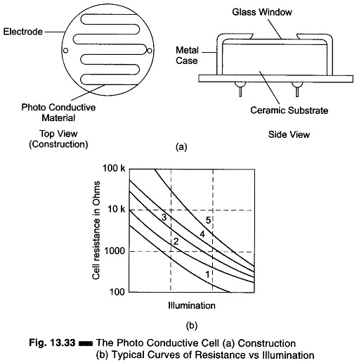
In this effect, the electrical resistance of the material varies with the amount of incident light, as shown in Fig. 13.33(b).
A typical construction is as shown in Fig. 13.33(a). The photo conductive material, typically Cadium sulphide, Cadium selenide or Cadium sulphoselenide, is deposited in a zig zag pattern (to obtain a desired resistance value and power rating) separating two metal coated areas acting as electrodes, all on an insulating base such as ceramic. The assembly is enclosed in a metal case with a glass window over the photo conductive material.
Photocells of these types are made in a wide range of sizes, from 1/8 in. in diameter to over 1 in. The small sizes are suitable where space is critical, as in punched card reading equipment. However, very small units have low power dissipation ratings.
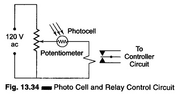
A typical control circuit utilizing a photo conductive cell is illustrated in Fig. 13.34. The potentiometer is used to make adjustments to compensate for manufacturing tolerances in photocells sensitivity and relay operating sensitivity.
When the photocell has the appropriate light shining on it, its resistance is low and the current through the relay is consequently high enough to operate the relay. When the light is interrupted, the resistance rises, causing the relay current to decrease enough to de-energies the relay.