7 Segment Led Display Working Principle:
In 7 Segment Led Display, it is usual to employ a single LED for each segment.
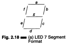
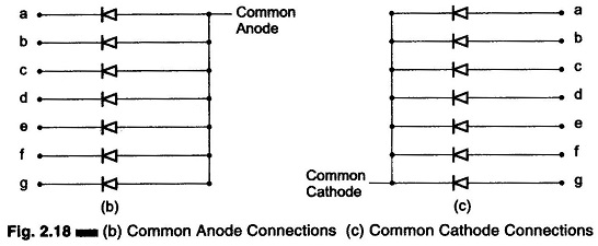
For conventional 7 Segment Led Display (including the decimal point, i.e. the 8th segment), the wiring pattern is simplified by making one terminal common to all LEDs and other terminals corresponding to different segments. The terminals can be either of the common anode (CA) form or common cathode (CC) form, shown in Figs 2.18 (b) and (c).
A typical static single digit 7 segment LED display system and multi-digit are shown in Figs. 2.18 (a) and (d).
Multi-digit display system may be static or dynamic.
Common anode type displays require an active low (or current sinking) configuration for code converter circuitry, whereas an active high (or current sourcing) output circuit is necessary for common-cathode LED type display.
Both multi-digit and segmental displays require a code converter; one code converter per character for static display systems and a single code converter for time shared and multiplexed dynamic display systems, which are illuminated one at a time.
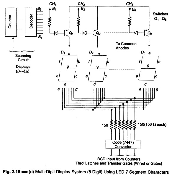
The typical circuit schemes described in the figures are only of the decimal numeric character. An 8 digit display system, operating on this principle and suitable for digital instrumentation is given in Fig. 2.18 (d).
It is also possible to generate hexadecimal numeric characters and conventional alphanumeric characters using 7 segment and 14 or 16 segment LED display units respectively, with a proper code converter. Both static and dynamic displays can be realized using LCDs, either in a common format (7 segment) or in single or multi character.
A chopped dc supply may be used, for simplicity, but conventionally an ac voltage is applied either to the common electrode or to the segment. Various segmental LCD driver circuits are displayed in Fig. 2.19.
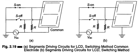
Referring to Figs 2.19 (a) and (b), it is seen that an ac voltage (Vac) is applied to either the common electrode or to the segment. High value resistances (R > 1M) are included in the circuit, as shown. The code converter controls the switches (S) . Vac is present across the selected segment and the common electrode when S is ON, and the voltage between any other segment (S-OFF) and the common electrode is zero. Hence the desired segments are energized, provided Vac has a magnitude greater than or equal to the operating voltage of the LCD.
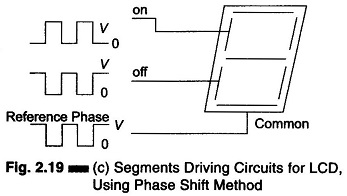
The basic operation of the phase shift method for driving the segment is shown in Fig. 2.19 (c). In this circuit, ac voltages of the same amplitude and frequency (not necessarily same phase) are supplied to the common electrode as well as the segments.
There will be a finite voltage drop between a segment and the common electrode only when the ac voltages applied are out of phase, and thus the selected segment is energised. On the other hand, when in-phase voltages are present, the voltage drop between a segment and the common electrode is zero, leading to the off state.