BCD to 7 Segment Decoder using IC 7447:
BCD to 7 Segment Decoder using IC 7447 are generally used as numerical indicators and consists of a number of LEDs arranged in seven segments as shown in the Fig. 15.1.
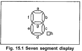
Any number between 0 and 9 can be indicated by lighting the appropriate segments. The 7-segment displays are of two types : common anode type and common cathode type.
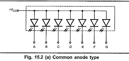
In common anode, all anodes of LEDs are connected together as shown in Fig. 15.2 (a) and in common cathode, all cathodes are connected together, as shown in Fig. 15.2 (b).
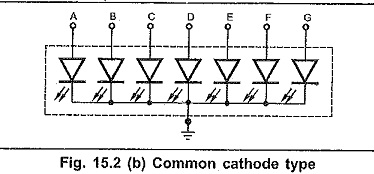
Fig. 15.3 shows a circuit to drive a single, BCD to 7 Segment Decoder using IC 7447, common anode LED display. For common anode, when anode is connected to positive supply, a low voltage is applied to a cathode to turn it on. Here, BCD to seven segment decoder, IC 7447 is used to apply low voltages at cathodes according to BCD input applied to 7447. To limit the current through LED segments resistors are connected in series with the segments. This circuit connection is referred to as a static display because current is being passed through the display at all times.
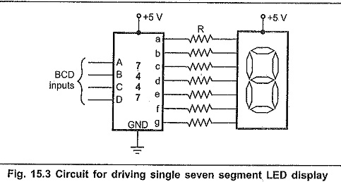
The value of the resistor in series with the segment can be calculated as follows :
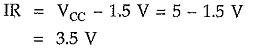
We know, VCC — drop across LED segment – IR = 0
Drop across LED segment is nearly 1.5 V.
Each LED segment requires a current of between 5 and 30 mA to light. Let’s assume that current through LED segment is 15 mA
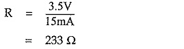
In practice, the voltage drop across the LED and the output of 7447 are not exactly predictable and the exact current through the LED is not critical as long as we don’t exceed its maximum current rating. Therefore, a standard value 220 Ω can be used.
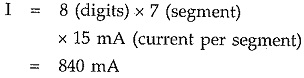
The static display circuits work well for driving just one or two LED digits. However, these circuits are not suitable for driving more LED digits, say 8 digits. When there are more number of digits, the first problem is power consumption. For worst-case calculations, assume that all eight digits with all segments are lit. Therefore, worst case current required is
A second problem of the static approach, is that each display digit requires a separate BCD to 7 segment decoder.
To solve the problems of the static display approach multiplexed display method is used. ‘Fig. 15.4 shows the 4 seven segment displays connected using multiplexed method. Here, common anode seven segment LEDs are used.
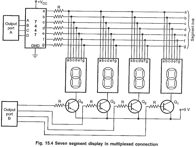
Anodes are connected to +5V through transistors. Cathodes of all BCD to 7 Segment Decoder using IC 7447 are connected in parallel and then to the output of 7447 IC through resistors. Looking at the Fig. 15.4, the question may occur in our mind that,”Aren’t all of the digits going to display the same number?” The answer is that they would show the same number only if all the digits are turned on at the same time. However, in multiplexed display the segment information is sent for all digits on the common lines (output lines of 7447), but only one display digit is turned on at a time. The PNP transistors connected in series with the common anode of each digit act as an ON and OFF switch for that digit. Here’s how the multiplexing process works.
The BCD code for digit 1 is first output from port A, to the 7447. The 7447, BCD to seven segment decoder outputs the corresponding seven segment code on the segment bus lines. The transistor Q1 connected to digit 1 is then turned on by outputting a low to that bit of port B. All of the rest of the bits of port B are made high to ensure no other digits are turned on. After 2ms, digit 1 is turned OFF outputting all highs to port B. The BCD code for digit 2 is then output to the port A, and bit pattern to turn on digit 2 is output on port B. After 2rns, digit 2 is turned off and the process is repeated for digit 3 and digit 4. After completion of turn for each digit, all the digits are lit again in turn.
With 4 digits and 2ms per digit we get back to digit 1 every 8 ms or about 125 times a second. This refresh rate is fast enough that, to our eye and due to persistence of vision all digits will appear to be lit all the time.
In multiplexed display, the segment current is kept in between 40 mA to 60 mA so that they will appear as bright as they would if not multiplexed. Even with this increased segment
current, multiplexing gives a large saving in power and hardware components. In chapter 14, we have already seen the interfacing of multiplexed displays using 8255 and 8279.