Working Principle of Digital Multimeter:
Analog meters require no power supply, they give a better visual indication of changes and suffer less from electric noise and isolation problems. These meters are simple and inexpensive. Digital meters, on the other hand, offer high accuracy, have a high input impedance and are smaller in size. They gives an unambiguous reading at greater viewing distances. The output available is electrical (for interfacing with external equipment), in addition to a visual readout. The three major classes of Working Principle of Digital Multimeter are panel meters, bench type meters and system meters.
All Working Principle of Digital Multimeter employ some kind of analog to digital (A/D) converters (often dual slope integrating type) and have a visible readout display at the converter output.
Panel meters are usually placed at one location (and perhaps even a fixed range), while bench meters and system meters are often multimeters, i.e. they can read ac and dc voltage currents and resistances over several ranges.
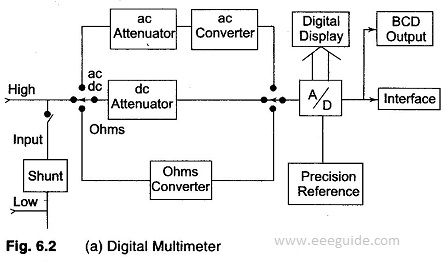
The basic circuit shown in Fig. 6.2 (a) is always a dc voltmeter. Current is converted to voltage by passing it through a precision low shunt resistance while alternating current is converted into dc by employing rectifiers and filters. For resistance measurement, the meter includes a precision low current source that is applied across the unknown resistance; again this gives a dc voltage which is digitised and readout as ohms.
Bench meters are intended mainly for stand alone operation and visual operation reading, while system meters provide at least an electrical binary coded decimal output (in parallel with the usual display), and perhaps sophisticated interconnection and control capabilities, or even microprocessor based computing power.
Block Diagram of Digital Multimeter:
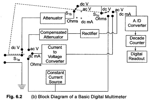
A basic Working Principle of Digital Multimeter (DMM) is made up of several A/D converters, circuitry for counting and an attenuation circuit. A basic Digital Multimeter Block Diagram is shown in Fig. 6.2 (b). The current to voltage converter shown in the block diagram of Fig. 6.2 (b) can be implemented with the circuit shown in Fig. 6.2 (c).
Current to Voltage Converter in Digital Multimeter:
The current to be measured is applied to the summing junction (Σi) at the input of the opamp. Since the current at the input of the amplifier is close to zero because of the very high input impedance of the amplifier, the current IR is very nearly equal to Ii, the current IR causes a voltage drop which is proportional to the current, to be developed across the resistors. This voltage drop is the input to the A/D converter, thereby providing a reading that is proportional to the unknown current.
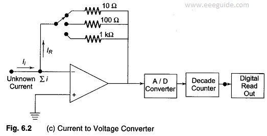
Resistance is measured by passing a known current, from a constant current source, through an unknown resistance. The voltage drop across the resistor is applied to the A/D converter, thereby producing an indication of the value of the unknown resistance.
Digital Panel Meter (DPM):
Digital panel meter are available in a very wide variety of special purpose functions. They have a readout range from the basic 3 digit (999 counts, accuracy of ± 0.1% of reading, ± 1 count) to high precision 43/4 digit ones (± 39,999 counts, accuracy ± 0.005% of reading ± 1 count). Units are available to accept inputs such as dc voltage (from microvolts range to ± 20 volts) ac voltage (for true rms measurement), line voltage, strain gauge bridges (meter provides bridge excitation), RTDs (meter provides sensor excitation), thermocouples of many types (meter provides cold junction compensation and linearisation) and frequency inputs, such as pulse tachometers.
Figure 6.3 shows some details of a high precision Digital Panel Meter unit with an input resistance of 109 Ω, ± 0.00250% resolution (10 μV), and ± 0.005% of reading ± 1 count accuracy, which uses a dual slope A/D conversion with automatic zero. The sampling rate is 2.5 per second when it is free running and a maximum of 10 per second when it is externally triggered.
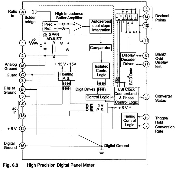
These meters can be obtained with a tri-state binary coded decimal output. Tri-state outputs provide a high impedance (disconnected) state, in addition to the usual digital high and low. This facilitates interconnection with the microcomputer data buses, since any number of devices can be serviced by a single bus, one at a time, disconnecting all except the two that are communicating with each other.
Bench Type Meters:
Bench type meters range from inexpensive hand held units with a 3½ digit readout and 0.5% accuracy, to 5½ digit (200,000 count) devices with 1 μV resolution. Digital nanovoltmeters are designed to measure extremely low voltages and they provide resolution down to about 10 nV (comparable analog meters go to about 1 nV).
Digital picoammeters measure very small currents and can resolve about 1 pA (analog instruments go to 3 femto (10-15) amperes). When extremely high input impedance is required for current, voltage, resistance or charge measurements, an electrometer type of instrument is employed.
Digital electrometer can resolve 10-17 A, 10 μV and 1 femto charge and measure resistance as high as 200 T Ω (Tera = 1012). The input impedance can be as high as 10,000 T Ω.
System Type Meters:
System type DVMs or DMMs are designed to provide the basic A/D conversion function in data systems assembled by interfacing various peripheral devices with DVM capabilities and their cost vary widely.
A microprocessor is used to provide several mathematical functions in addition to managing the meter operations. A modified dual slope A/D converter is used with selectable integration times, ranging from 0.01 to 100 power lines cycle. At maximum speed (330 readings per second) accuracy is ± 0.1%, while 0.57 readings per second gives a 6½ digit resolution and 0.001% accuracy. Ac and dc voltages and resistance modes are available. The mathematical functions include the following.
- Null
- First reading is subtracted from each successive reading and the difference is displayed. (The first reading can be manually entered from the key-board.)
- The function STAT accumulates reading and calculates mean and variance, (STAT-Statistics).
- With dBm (R), the user enters the resistance and then all readings are displayed as power dissipated in R in decibel units (referred to 1 mV).
- With THMS°F (voltmeter in ohms range), the temperature of a thermistor probe is displayed in degrees Fahrenheit or Centigrade (THMS -Temperature of Thermistor)
- The function (X – Z)/Y provides offsetting and scaling with user entered Z and Y constants (where X is the reading).
The function 100 x (X – Y)/Y determines the percentage deviation, and 20 log X/Y displays X in decibels relative to the value of Y. An internal memory (RAM) can be used to store the results of measurements and programs for taking the measurements.