Digital Tachometer Working Principle:
Digital Tachometer Working Principle technique employed in measuring the speed of a rotating shaft is similar to the technique used in a conventional frequency counter, except that the selection of the gate period is in accordance with the rpm calibration.
Let us assume, that the rpm of a rotating shaft is R. Let P be the number of pulses produced by the pick up for one revolution of the shaft. Therefore, in one minute the number of pulses from the pick up is R x P. Then, the frequency of the signal from the pick up is (R x P)/60. Now, if the gate period is G s the pulses counted are (R x P x G)/60. In order to get the direct reading in rpm, the number of pulses to be counted by the counter is R. So we select the gate period as 60/P, and the counter counts

and we can read the rpm of the rotating shaft directly. So, the relation between the gate period and the number of pulses produced by the pickup is G = 60/P. If we fix the gate period as one second (G = 1 s), then the revolution pickup must be capable of producing 60 pulses per revolution.
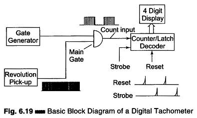
Figure 6.19 shows a schematic diagram of a digital tachometer.