Cascaded Differential Amplifier Working Principle:
Cascaded Differential Amplifier Working Principle – Figure 20.53 gives an idea of how differential amplifiers can be cascaded to give an op-amp. Here the output of first section differential amplifier is fed to the second section, which is again a differential amplifier. This provides the best common mode rejection ratio and differential voltage gain.
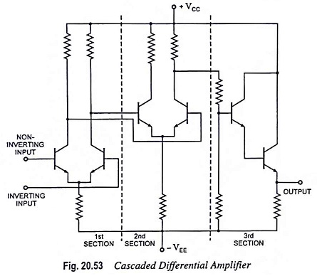
The third section of op-amp is a common collector or common emitter follower stage which has low output impedance. The output is single ended, as shown in Fig. 20.53. It can provide only one phase with respect to ground and that is why two inputs are referred to inverting and noninverting inputs.
The noninverting input will be in phase with the output terminal. The inverting input will be 180° out of phase with the output terminal.
Applications and Advantages:
In many cases the matching of transistors as well as resistor values is necessary for proper functioning of the differential stages. That is why the use of transistor array like CA3086 is recommended. This transistor array have inherent advantages unique to IC circuits such as compactness, ease of physical handling and electrical and thermal matching.