Swamping Resistor in Differential Amplifier:
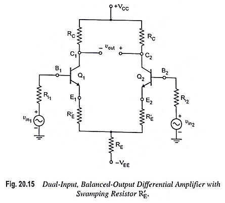
The dependence of the voltage gain of the differential amplifiers on variations in ac emitter resistance r′e can be reduced and also the linearity range of the differential amplifiers can be increased if external resistors R′E are connected in series with each emitter, as shown in Fig. 20.15 (Dual input, balanced-output differential amplifier). Usually, the resistor R′E is large enough to swamp the effect of ac emitter resistance r′e and, therefore, R′E is sometimes referred to as a Swamping Resistor in differential amplifier.
The emitter current in each transistor may be determined by KVL around the base-emitter loop of transistor Q1 with vin1 = 0 and vin2 = 0 V.
Omitting the subscripts because of symmetry between the two halves of the differential amplifier.
Substituting IB ≡ IE/βdc in above equation, we have
The above Eq. (20.39) is also valid for the remaining three configurations with swamp resistor R′E.
The voltage between collector and emitter, VCE is given by Eq. (20.6) and is given here for convenience
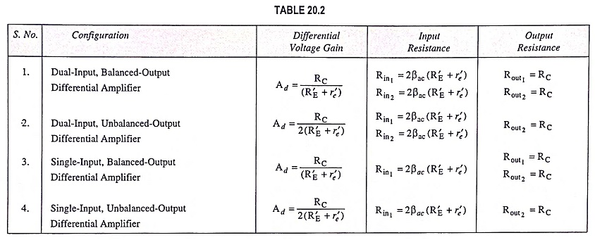
When external resistors R′E are inserted in each emitter lead, the new voltage gain and new input resistance can be obtained for any configuration simply by replacing r′e by (R′E + r′e). However, output resistance with or without R′E is the same.
The values of differential voltage gain, input resistance and output resistance for the different configurations of swamping resistor in differential amplifier are summarized below (Table 20.2) in tabular form.


