Three Terminal IC Voltage Regulators – Block Diagram:
The latest generation of IC voltage regulators has devices with only three pins: one for the unregulated input voltage, one for the regulated output voltage, and one for ground. The new devices can supply load current from 100 mA to more than 5 A. Available in plastic or metal packages, these three-terminal voltage regulators have become extremely popular because they are inexpensive and easy to use. Aside from a couple of bypass capacitors, the new three terminal IC voltage regulators do not need any external component.
The integrated three-terminal voltage regulators typically incorporate many of the functions discussed so far in a single package, as illustrated in Fig. 43.21.
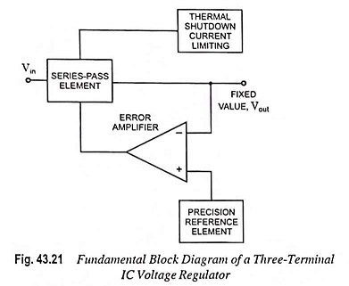
The error amplifier is used to maintain a constant voltage through a negative feedback. The internal voltage reference is tightly controlled during the fabrication of IC. So, the nominal output voltage of most of the three terminal voltage regulators has tolerances that range from ±6% to better than ±2%. The series-pass element is driven by the output of the error amplifier. It acts as an automatically controlled variable resistor. Its resistance varies as required for maintaining the output voltage constant. The series-pass element is typically a BJT that is rated to pass the maximum load current.
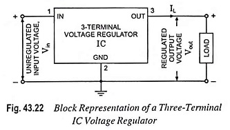
The basic connection of a three terminal IC voltage regulators to a load is shown in Fig. 43.22. The fixed voltage regulator has an unregulated dc input voltage Vin, applied to one input terminal, a regulated output dc voltage, Vout from a second terminal, with the third terminal connected to ground.