Sweep Frequency Generator – Block Diagram and its Workings:
A Sweep Frequency Generator is a special type of signal generator which generates a sinusoidal output whose frequency is automatically varied or swept between two selected frequencies. One complete cycle of the frequency variation is called a sweep. The rate at which the frequency is varied can be either linear or logarithmic, depending upon the design of a particular instrument. However, the amplitude of the signal output is designed to remain constant over the entire frequency range of the sweep.
Sweep frequency generators are primarily employed for measurement of responses of amplifiers, filters, and electrical components over various frequency bands. The frequency range of a sweep frequency generator usually extends over three bands, 0.001 Hz-100 kHz (low frequency to audio), 100 kHz-1,500 MHz (RF range), and 1-200 GHz (microwave range). Performance of measurement of bandwidth over a wide frequency range with a manually tuned oscillator is a time consuming task. With the use of a sweep frequency generator, a sinusoidal signal, that is automatically swept between two chosen frequencies, can be applied to the circuit under test and its response against frequency can be displayed on an oscilloscope or X-Y recorder.
Thus the measurement time and effort is considerably reduced. Sweep frequency generators may also be employed for checking and repairing of amplifiers used in TV and radar receivers.
The block diagram of an electronically tuned sweep frequency generator is shown in Fig. 30.147.
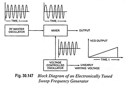
The main component of a sweep frequency generator is a master oscillator, usually an RF type, with several operating ranges which are selected by a range switch. The frequency of the output signal of the signal generator may be varied either mechanically or electronically.
In the mechanically varied models, the frequency of the output signal of the master oscillator is varied (tuned) by a motor driven capacitor.
In the electronically tuned models, the frequency of the master oscillator is kept fixed and a varying frequency signal is produced in another oscillator, called the voltage controlled oscillator (VCO). The VCO contains an element whose capacitance depends upon the voltage applied across it. This element is employed for varying the frequency of the sinusoidal output of the VCO. The output of the VCO is then combined with the output of the master oscillator in a special electronic device, called the mixer. The output of the mixer is sinusoidal, whose frequency depends on the difference of frequencies of the output signals of the master oscillator and VCO. For example, if the master oscillator frequency is fixed at 10.00 MHz and the variable frequency is varied between 10.01 MHz to 35 MHz, the mixer will give sinusoidal output whose frequency is swept from 10 kHz to 25 MHz.
The sweep rates of sweep frequency generators can be adjusted to vary from 100 to 0.01 seconds per sweep. A voltage varying linearly or logarithmically according to sweep rate can be used for driving the X-axis of an oscilloscope or X-Y recorder synchronously. In the electronically tuned sweep generators, the same voltage which drives the VCO serves as this voltage.
The frequency of various points along the frequency response curve can be interpolated from the values of the end frequencies if it is known how does the frequency vary (i.e., linearly or logarithmically). For more accuracy markers can be employed.