Block Diagram of a General Purpose CRO and its workings:
The modern time-domain General Purpose CRO, regardless of its sophistication, consists of the following main units.
- Cathode ray tube (CRT) — display device.
- Power supplies and internal circuits.
- Vertical amplifier (include probe or transducer to obtain an electrical signal).
- Time base or sweep generator.
- Horizontal amplifier.
- Delay line.
- Deflection plates (i) Vertical (ii) Horizontal
- Trigger or synchronizing circuit (to start each sweep at a desired point in time for the signal to be displayed).
- Electron gun.
- Phosphor screen.
The instrument employs a cathode ray tube (usually abbreviated as CRT), which is the heart of the oscilloscope. It generates the electron beam, accelerates the beam to a high velocity, deflects the beam to create the image, and contains a phosphor screen where the electron beam eventually becomes visible. For accomplishing these tasks various electrical signals and voltages are required, which are provided by the power supply circuit of the oscilloscope.
Low voltage supply is required for the heater of the electron gun for generation of electron beam and high voltage, of the order of few thousand volts, is required for cathode ray tube to accelerate the beam. Normal voltage supply, say a few hundred volts, is required for other control circuits of the oscilloscope.
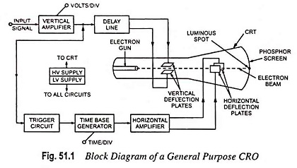
Horizontal and vertical deflection plates are fitted between electron gun and screen to deflect the beam according to input signal. Electron beam strikes the screen and creates a visible spot. This spot is deflected on the screen in horizontal direction (X-axis) with constant time dependent rate. This is accomplished by a time base circuit provided in the General Purpose CRO. The signal to be viewed is supplied to the vertical deflection plates through the vertical amplifier, which raises the potential of the input signal to a level that will provide usable deflection of the electron beam.
Now electron beam deflects in two directions, horizontal on X-axis and vertical on Y-axis. A triggering circuit is provided for synchronizing two types of deflections so that horizontal deflection starts at the same point of the input vertical signal each time it sweeps. A basic block diagram of a General Purpose CRO is shown in Fig. 51.1.