Analog Storage Oscilloscope Block Diagram and Its Workings:
Storage targets can be distinguished from standard phosphor targets by their ability to retain a waveform pattern for a long time (10 to 150 hours after the pattern is produced on the screen). In a conventional CRT the persistence of the phosphor varies from a few milliseconds to several seconds as a result of which where persistence of the screen is smaller than the rate at which the signal sweeps across the screen, the start of the display would fade before the end is written. Analog storage oscilloscope uses the phenomenon of secondary electron emission to build up and store electrostatic charges on the surface of an insulated target. Such Analog Storage Oscilloscope are widely used (i) for real-time observation of events that occur only once and (ii) for displaying the waveform of a very low frequency (VLF) signal.
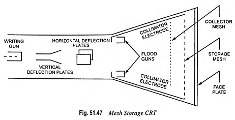
A mesh storage CRT, illustrated in Fig. 51.47, contains a storage mesh, flood guns and a collimator, in addition to all the elements of a standard CRT. The storage mesh that is the storage target behind the phosphor screen is a conductive mesh covered with dielectric material consisting of a thin layer of material such as magnesium fluoride. The writing gun is a high energy electron gun similar to the conventional gun, providing a narrow focused beam which can be deflected and used to write the information to be stored. The writing gun etches a positively charged pattern on the storage mesh or target by knocking off secondary emission electrons. This positively charged pattern remains exactly in the position on the storage target where it is deposited. This is due to the excellent insulating property of the magnesium fluoride coating on the storage target. The electron beam, which is deflected in the conventional manner both in horizontal and vertical directions traces out the wave pattern on the storage mesh.
In order to make the pattern visible, even after several hours, special electron guns, known as the flood guns, are switched on. The flood guns are of simple construction and are placed inside the CRT in a position between the deflection plates and the storage target and they emit low-velocity electrons covering a large area towards the screen. The electron paths are adjusted by the collimator electrodes consisting of a conductive coating on the inside surface of the CRT. The collimator electrodes are biased so as to distribute the flood gun electrons evenly over the target surface and cause the electrons to be perpendicular to the storage mesh.
Most of the flood electrons are stopped and collected by the collector mesh and, therefore, never reach the phosphor screen. Only electrons near the stored positive charge are pulled to the storage target with sufficient force to hit the phosphor screen. The CRT display, therefore, will be exact replica of the pattern which was initially stored on the target and the display will remain visible as long as the flood guns operate. For erasing of the pattern on the storage target, a negative charge is applied to neutralize the stored positive charge.
For achieving variable persistence, the erase voltage is applied in the form of pulses instead of a steady dc voltage. By varying the width of these pulses the rate of erase is controlled.
Variable persistence storage finds many applications like the storage of an entire waveform of a slow moving signal, which then fades before the next is written. It may also be used for storing several traces before the first one fades in order to observe how the signal varies with time.