Step Down Chopper with RLE Load Working Principle:
The choppers are widely employed for speed control of dc motors in industrial and traction drives. Figure 27.30 (a) shows the basic Step Down Chopper with RLE Load for the control of a dc series motor. The Step Down Chopper with RLE Load is shown to consist of a force-commutated thyristor, it could well be a transistor switch. It offers one-quadrant drive [Fig. 27.30 (b)]. Armature current is assumed continuous and ripple free. The waveforms for the source voltage V, armature terminal voltage va, armature current ia, supply current i and freewheeling-diode current iDFW are shown in Fig. 27.30 (c). From these waveforms we have
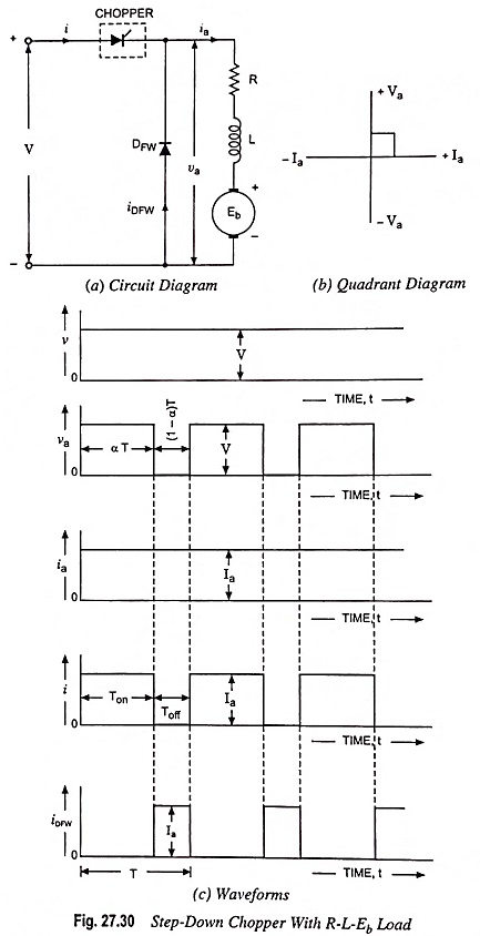
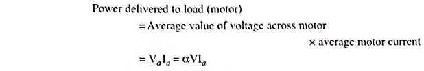
Average value of voltage across motor,
![]()
where α = Duty cycle = Ton/T and f = Chopping frequency = 1/T


For the motor armature circuit,
![]()
or Motor speed,

From above Eq. (27.48) it is obvious that the armature terminal voltage and therefore, speed of the dc motor can be controlled by varying the duty cycle α of the chopper.
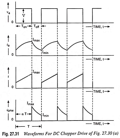
So far, armature current ia has been assumed ripple free and accordingly waveforms in Fig. 27.30 (c) are drawn. But in practice, the motor armature current increases during chopper on period and decreases during chopper off period, as illustrated in Fig. 27.31.
For R-L-Eb type of load, Eb is load voltage (back emf of motor). When the chopper is switched on for a period Ton and power is supplied to R-L-Eb load. By using Kirchhoff’s voltage law (KVL) in the loop consisting of V, chopper and R-L-Eb load, we have
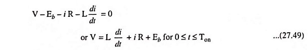
When chopper is off, the load current continues flowing through the freewheeling diode due to energy stored in the inductor. The KVL for the loop containing R-L-Eb and DFW yields
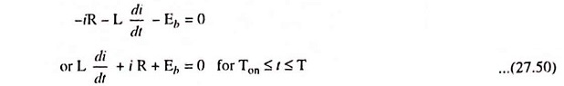
The above Eqs. (27.49) and (27.50) can be solved by using Laplace transform. It is seen from Fig. 27.31 that initial value of load current is Imin for Eq. (27.49) and Imax for Eq. (27.50).
So Laplace transform of Eqs. (27.49) and (27.50) we have
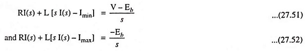
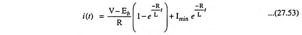
From Eq. (27.51), we have

Laplace inverse of above equation is
Similarly the time-domain expression for current from Eq. (27.52) is
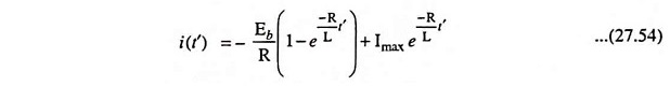
Here
- R = Armature resistance Ra + series field resistance Rse
- L = Armature inductance + series field inductance Lse.
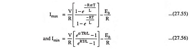
The values of maximum current Imax and minimum current Imin can be determined by using the fact that i (t) = Imin when t = 0 and i (t’) = Imax when t’ = 0. The values are found to be