What is Thermal Runaway and Heat Sink?
The maximum average power PC max which a transistor can dissipate depends upon the construction of the transistor and may lie in the range of a few milliwatts and 200 W. This maximum power is limited by the temperature that the collector-base junction withstand. For silicon transistor this temperature is in the range of 150-225°C and for germanium it is between 60°C and 100°C. The maximum power dissipation is usually specified for the transistor enclosure (or casing) of ambient temperature of 25°C. The junction temperature may rise either because of rise in ambient temperature or because of self heating. The problem of self heating arises due to dissipation of power at the collector junction. The leakage current ICBO is extremely temperature dependent and increases with the rise in temperature of collector-base junction. An increase in ICBO causes an increase in collector current IC considerably. With the increase in collector current IC, collector power dissipation increases which raises the junction temperature that leads to further increase in collector current IC. The process is cumulative and may lead to the eventual destruction of the transistor. This phenomenon is known as thermal runaway of the transistor. In practice, thermal runaway is prevented in a well designed circuit by using stabilization circuitry.
When the power dissipation at the collector-base junction of a transistor is small, as in case of a small-signal transistor, the surface area of the transistor case is normally large enough to allow all of the heat to escape. But for the large power dissipation that can occur in large power transistor the transistor surface area is not large enough and junction temperature may rise to a dangerous level. However, power handling capacity of a transistor can be increased by making suitable provision for rapid conduction of heat away from the transistor junction. This is achieved by using a sheet of metal called the heat sink which increases the area of contact with the atmosphere.
Heat sink is a direct practical means of combating the undesirable thermal effects e.g., thermal runaway. It may be noted that the ability of any heat sink to transfer heat to the surroundings depends upon its material, volume, area, shape, contact between case and sink and movement of air around the sink.
For achieving efficient heat dissipation heat sinks of different types are employed. A few of these are shown in Fig. 10.70.
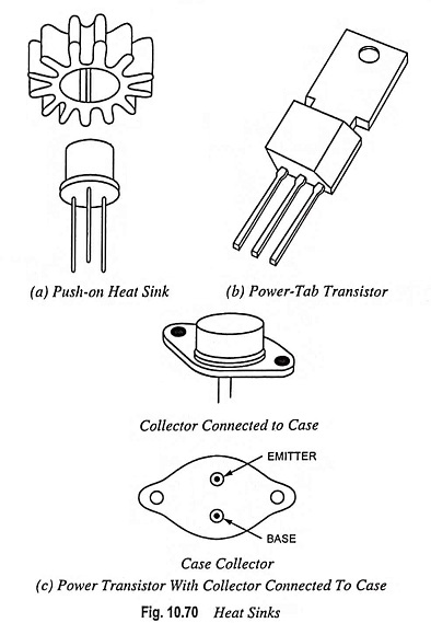
One type of heat sink, called the push-on heat sink, is shown in Fig. 10.70(a). When this is pushed on to the transistor case, heat radiates more quickly because of the increased surface area of the fins.
Power tab transistor outline is shown in Fig. 10.70(b). A metal tab provides a path out of the transistor for heat. This metal tab can be fastened to the chassis of electronic equipment. Because the chassis is a massive heat sink, heat can easily escape out from the transistor to the chassis.
Large power transistors like shown in Fig. 10.70(c) have the collector connected to the case to dissipate heat as easily as possible. The transistor case is then fastened to the chassis. To prevent the collector from shorting to chassis ground, a thin mica washer is used between the transistor case and the chassis. The important idea here is that heat can escape out from transistor at a faster rate, which means that the transistor has a higher power rating at the given ambient temperature. Sometimes, the transistor is fastened to a large heat sink with fins; this is even more efficient in heat dissipation from transistor.
Finned aluminium heat sinks yield the best heat transfer per unit cost.
For maximum efficiency a heat sink (i) is kept in good thermal contact with the transistor case (ii) is made with the largest possible surface area (iii) is painted black and (iv) is mounted in such a position that free air can flow past it.
The noteworthy point here is that the use of heat sink may not be sufficient to avoid thermal runaway under all conditions. In designing a transistor circuit, consideration should also be given to the choice of (i) operating point (ii) ambient temperatures which are likely to be encountered and (iii) the type of transistor e.g., metal case transistors are more readily cooled by conduction than plastic ones. Circuits may be designed to compensate automatically for temperature variations and thus stabilize the operation of the transistor components.