UJT as Over Voltage Detector Circuit Diagram:
UJT as Over Voltage Detector Circuit Diagram – A simple dc overvoltage detector circuit is given in Fig. 26.96. It operates on the fact that the device remains switched off as long as the input voltage remain less than the peak point voltage VP of the UJT and as soon as input voltage exceeds VP, the device is switched on.
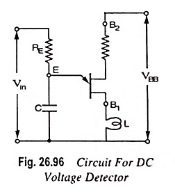
Let the input voltage Vin to be kept constant. For it VBB is to be chosen in such a way that this is slightly lesser than Vin. As soon as Vin exceeds VP, then UJT is switched on, and consequently the capacitor commences discharging through low resistance path E and B1.
The current flowing in pilot lamp L lights it, which is an indication of an overvoltage across the circuit.