Zero Crossing Detector Circuit:
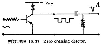
Zero Crossing Detector Circuit basically involves the sine to square wave conversion by a level detector circuit followed by a pulse circuit, which consists of one shot monostable circuit or a differentiator. The zero crossing detection is associated with the production of a pulse at the particular zero crossing. Figure (10.37) shows the circuit for Zero Crossing Detector Circuit.
Output Devices:
The output devices have to perform many duties such as operation of breaker, intertripping, alarm and remote indication, etc. noncritical switching units are most suitable as output devices since they are associated with two or more electrically separate contact operations.
Amongst the static units the thyristor is an excellent means for tripping the circuit breaker from a low power signal of short duration. It operates with signals of microsecond duration but once triggered stays in conduction until broken by a switch.
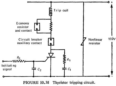
A typical thyristor tripping circuit is shown in Fig. (10.38). R1 and C1 are included to prevent excessive surges appearing across the thyristor. The small resistance R1 limits the capacitor-discharge current on operation. The filter circuit connected to the gate electrode has the capacitor C2 connected immediately adjacent to the thyristor, to minimize pickup voltages on the gate electrode.
Reed relays though not static strictly speaking are very much suitable to semiconductor circuits. If properly designed they can also perform fast tripping of circuit breaker, provided the power factor and ratings of trip circuit are specified. The reed relays being very light in weight are susceptible to maloperation due to shock and vibrations.