What is Capacitor in Electronics?:
What is Capacitor in Electronics? – Capacitor is a two-terminal element that has the capability of charge storage and, consequently, energy storage. The stored energy can be fully retrieved.
The current through the capacitor is proportional to the derivative of voltage across it and is given by expression
![]()
where C has the unit of Farads, the practical unit being a microfarad (μF) because a Farad is physically a large unit. Integrating above Eq. (1.8) we have
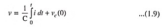
where
- vc(0) = Capacitance voltage at t = 0
For an initially uncharged capacitor vc(0) = 0, so that
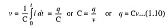
The proportionality constant C expresses the charge-storing property of the element and is called the capacitance. With q in coulombs and v in volts, the capacitance C is in Farads (abbreviated F). A Capacitor in Electronics is a physical element which exhibits the property of capacitance.
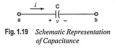
The schematic representation of capacitance, in which current and voltage reference directions are indicated, is depicted in Fig. 1.19. In this figure and Eqs. (1.8) and (1.10), a voltage drop exists in the direction of flow of current. Charge flow from a higher potential to a lower potential i.e. from plus to minus, signifies that energy can be removed from the circuit and stored. The capacitive effect may be thought of as opposing a change of voltage.
The power associated with a capacitance is
![]()
Energy stored in the capacitance may be had by integrating above Eq. (1.11) as
![]()
A Capacitor in Electronics offers low impedance to ac but very high impedance to dc. So capacitors are used to couple alternating voltage from one circuit to another circuit and at the same time to block dc voltage from reaching the next circuit. It is also employed as a bypass capacitor where it passes the ac through it without letting the dc to go through the circuit across which it is connected. A capacitor forms a tuned circuit in series or in parallel with an inductor.
Capacitor in Electronics are used for waveform generation, filtering, blocking and bypass applications. They are used in integrators and differentiators. In combination with inductors, they make possible sharp filters for separating desired signals from background.
To a first approximation, capacitors are devices that might be considered simply frequency-dependent resistors. Thus they may be used to make frequency-dependent voltage dividers.
A capacitor consists of two conducting plates, separated by an insulating material, called the dielectric. Capacitors, like resistors and inductors, can either be fixed or variable. Some of the commonly used fixed capacitors are mica, ceramic, paper, plastic-film and electrolytic capacitors.
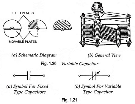
Variable capacitors are mostly air-gang capacitors. An elementary variable capacitor consists of two sets of copper or aluminium plates (which may have the shape of half discs). Each set is mounted on a common shaft, one set being fixed and other, which interleaves with the former, being movable. The capacitance of the capacitor can be easily varied by varying the degree of interleaving, which is possible by rotation of movable plate shaft. Such variable-capacitance, air capacitors, shown in Fig. 1.20, are widely used in radio work. Symbols for fixed type and variable type capacitors are given in Figs. 1.21(a) and 1.21(b) respectively.
Capacitors employed in power supplies of electronic and radio equipment may have values ranging from a few microfarads to several thousand microfarads. The capacitors used in the tuning circuits of the TV receivers may be as small as 10-20 pF.
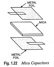
Mica Capacitors: Mica capacitors are built in round, rectangular, or irregular shapes. They are constructed by sandwiching layers of metal foil and mica, as shown in Fig. 1.22. Sometimes silver is deposited on the mica in lieu of metal foil. The resulting stack of metal and mica sheets is firmly clamped and encapsulated in a plastic package.
Mica capacitors possess very small leakage current (leakage resistance being of the order of 1,000 MQ) and dissipation factors. Available capacitance ranges are 1 pF to 0.1 μF with tolerances of ± 1 to ± 20 per cent. The capacitance is limited to this relatively small upper value because mica is not flexible enough to be rolled in tubes. As a result, the size of mica capacitor structures cannot be markedly reduced.
Mica capacitors are used as precision capacitors because of their small tolerances and high stability under temperature. They are also employed in such high-frequency applications as oscillator tuning and filter construction, where small capacitance values and low dissipation factors are desirable. Finally, high-voltage applications are often best served by mica capacitors.
Mica capacitors have no polarity preference and their capacitance value and other characteristics are often indicated by a colour-code scheme printed on their package.
Mica capacitors are made with dc voltage ratings from a few hundred to many thousands of volts and with radio-frequency current ratings up to about 50 A.
Ceramic Capacitors: Ceramic capacitors are quite suitable for generation of large powers (currents up to 150 A at voltages up to 5,000 V) at radio frequencies.
There are two different types of ceramic capacitors being built—the low-loss, low-dielectric-constant type, and the highdielectric-constant type. The low-loss types have a very high leakage resistance (1,000 MΩ) and can be employed in high-frequency applications almost as mica capacitors.
The high-dielectric-constant types provide a large capacitance value in a small volume. However, their values of capacitance can change strongly with variations of temperature, dc voltage and frequency. This is due to the fact that the dielectric constant of such capacitors are highly dependent on these variables (temperature, dc voltage and frequency). Thus, this type of capacitor is only suitable if an exact capacitance is not required (such as in circuit coupling or bypass applications). Capacitance values of the high-dielectric-constant types range from 100 pF to 0.1 μF. A typical tolerance range is +100 per cent to –20 per cent of its stated value.
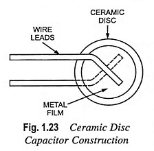
The ceramic capacitors may be of disc or tubular type. The disc type of construction used to build ceramic capacitors is shown in Fig. 1.23. A ceramic disc or plate is coated with metal (such as copper or silver) on both sides. During the manufacture of the capacitor, tinned wire leads are also attached to each plate. Then the entire unit is packaged in a coating of plastic or ceramic to protect it from moisture and other environmental conditions. The capacitance value is printed directly on the body, or a colour code is used. The colour coding is similar to that used for the resistances. Ceramic capacitors possess no required voltage polarity.
In tubular ceramic capacitors, the inner and outer surfaces of a hollow ceramic tube are coated with silver and form the two plates of the capacitor.
Ceramic capacitors are used primarily as coupling and bypass portions of radio frequency circuits rather than frequency determining elements. Specially designed ceramic capacitors are employed in resonant circuits.
Paper Capacitors: Paper capacitors are the most widely used type of capacitors. Their popularity is due to their low cost and the fact that they can be built in a broad range of capacitance values (500 pF to 50 μF). Furthermore, they can be designed to withstand very high voltages (several thousand volts). However, the leakage currents of paper capacitors are high and their tolerances are relatively poor (±10 to 20 per cent). Their leakage resistance is of the order of 100 MΩ. These limitations restrict their use in some applications. It size permits, the capacitance value and voltage are usually printed on the capacitor body. For small units, a colour code is employed. When the colour code is not used, a band (usually black) is often printed on the tube nearest the lead that is connected to the outer metal sheet. This lead should always be connected to the circuit lead of lower potential.
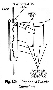
Many paper capacitors are of a cylindrical shape because they are made by rolling a sandwich of metal and impregnated paper sheets into a tube. Axial leads are attached to each metal sheet, and the tube is encapsulated in waxed paper or plastic, as illustrated in Fig. 1.24.
Various substances such as oil, wax or plastic are used to soak the paper. If paper deposited with thin metal films is used rather than separate metal sheets, the volume per unit of capacitance can be reduced by 50 per cent and the leakage current reduced by 90 per cent. Unfortunately, this creates a resulting structure which is more prone to rupture by high-voltage transients.
Special oil-filled paper capacitors are made which have high capacitance values and high breakdown or rupturing voltages. These types are usually mounted on metal cases and have ceramic insulators surrounding the input leads. Such high-voltage paper capacitors are employed primarily in certain power-supply and transmitter circuits.
Paper capacitors can be used for both dc and ac circuits. Paper capacitors are gradually being replaced by metallized polypropylene and polyester films with lower cost, smaller size and lower power factor.
Plastic-Film Capacitors: Plastic-film capacitors are constructed in basically the same way as paper capacitors, except that a thin sheet of plastic (such as Mylar, Teflon, or polyethylene) is employed as dielectric. This dielectric improves the properties of the capacitor by minimizing leakage currents, even at temperatures of up to 150-200°C. Their other characteristics are similar to those of paper units. However, the cost is higher for plastic units, so they are not usually employed except when a paper capacitor cannot meet the design specifications. Commercial plastic-film capacitors are manufactured in ranges between 500 pF and 10 μF.
Electrolytic Capacitors: Electrolytic capacitors are usually made of aluminium or tantalum because they form oxides with very high dielectric strengths. The basic structure of the aluminium electrolyte capacitor consists of two aluminium foils, one of which is coated by an extremely thin oxide. The oxide is grown on the metal by a process of applying a voltage to the capacitor; the process is called forming. The thickness of the oxide depends on the forming voltage. Between the foils is an electrolyte solution soaked into paper. This electrolyte is a conductor and serves as an extension of the nonoxidized metal foil. Since it is a fluid, the electrolyte can butt up directly against the oxide dielectric. The two oppositely charged plates are then effectively separated by only an extremely thin oxide film which possesses an extremely high dielectric constant.
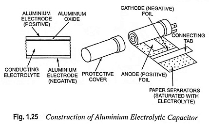
Once the oxide is formed, the foils are rolled into a tube, and the piece of foil without the oxide is connected to the capacitor’s exterior package. This lead serves as the negative connection to the capacitor. The other lead is marked by a “+” on the capacitor body and must be connected to the positive terminal of the circuit in which it is employed.
It needs to be strongly emphasized that the electrolytic capacitor should only be connected in a circuit with the proper polarities. If one connects the positive lead of the capacitor to the negative lead of a circuit, chemical action by the electrolyte will rupture the oxide dielectric and destroy the capacitor. (With reversed polarity, the oxide no longer acts like an insulator and as a result, a substantial leakage current can flow and disintegrate the oxide). In addition, as for other capacitors, the rated voltage must not be exceeded. For the largest capacitance values, the maximum voltage will be small because the oxide layer is so thin.
Electrolytic capacitors have the largest capacitance values per volume of element of any capacitor type. But they also possess very large leakage current values. These properties limit their use to special applications. For example, in transistor circuits, large capacitances in a small volume are desirable, but leakage currents or exact capacitance values are not necessarily critical. Thus electrolytic capacitors are suitable for some of these circuits. Electrolytic capacitors are available in values ranging from 1 μF to 500,000 μF. However, their corresponding leakage resistances are only about 1 MΩ.
Non-polarised electrolytic capacitors can be constructed for use in ac circuits. In effect, these are two polarised capacitors placed in series with their polarities reversed.
Colour Coding of Capacitors: Manufacturers today usually use letters of the alphabet and numbers (alphanumerics) stamped on either the disc or tubular body for indication of specifications of capacitors, as depicted in Fig. 1.26. This coding is known as alphanumeric coding.
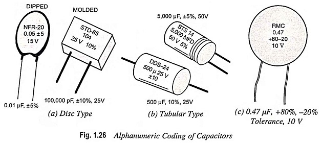
The tubular type, which tends to be larger in size, is the easier of the two since the information is basically uncoded. The value of capacitance in μF or pF, tolerance in percentage, and voltage rating in volts are printed on all sizes of tubular cases. The remaining letters or numbers are merely manufacturer’s codes for case size, series and the like
With disk capacitors (dipped or molded), as seen in Fig. 1.26 (a), certain rules have to be followed when decoding the notations. Many Capacitor in Electronics of this type do not indicate the unit of capacitance; in this situation, try to locate a decimal point. Existence of decimal point, for example 0.1 or 0.001, indicates the value in μF. In case, no decimal point exists, for example 20 or 240, the value is in picofarads.
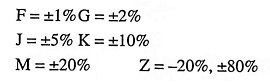
If no decimal point is present and three digits exist and last digit is zero, the value is as stands and in pF. If the third digit is a number other than 0 (1 to 9), it is a multiplier and defines the number of zeros to be added to the pF value. The tolerance of the capacitor is sometimes clearly indicated, for instance ±5 or 10%; in other cases a letter designation is used, like
Unfortunately, there does not seem to be a standard among capacitor manufacturers, which can cause confusion when trying to determine the value of capacitance. Thus, if you are not completely sure, you should always consult technical data or information sheets from the manufacturer.
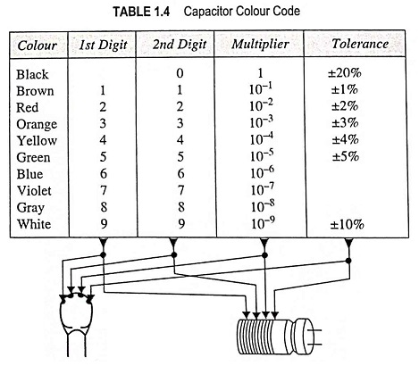
Table 1.4 illustrates the capacitors colour code, which is almost identical to the resistor colour code except for certain tolerances.
Failure of Capacitors: Capacitors are responsible for a substantial fraction of failures in service of electronic equipment with a reliability that is somewhere between that of discrete semiconductors and resistors. It is, therefore, important to know why capacitors fail and how the reliability can be enhanced. This concerns both the designer and the service engineer, because if a unit is known to fail frequently because of a capacitor problem, the capacitor should be replaced with one that can be expected to have a longer life.
Capacitor failures can be classified as open circuits, short circuits and leakage failures, and all three can be caused by the most common of all capacitor problems—internal sparking. Sparking can either evaporate metal contacts, causing an open circuit, or it can penetrate into a dielectric, causing short circuit. Plastic dielectrics can charge under heavy sparking, creating a carbon crack which forms a short circuit. Leakage failure is less common but can be caused by internal short circuit paths or by external paths (around the side of the dielectrics).
The main cause of premature capacitor failure are excessive voltage, excessive current, or excessive temperature, or combinations of all three. Combination of parameters can be particularly damaging, because though a capacitor may be rated for operation up to 120 °C and for 100 V working this does not imply that a voltage of 100 V can be used at a temperature of 120 °C. Mica and ceramic types are less likely to be affected by running at extremes of their parameters for short periods, but plastic dielectrics have to be treated with much more care, and electrolytes should always be conservatively rated. Sudden charging and discharging can be damaging to capacitors, and is the reason for so many types of capacitor manufacturer quoting the maximum rate of rise and fall of voltage.
The power factor or dissipation factor for a capacitor is seldom important for dc applications, but when a capacitor is used to handle ac, particularly high frequency ac, then a poor power factor can cause self heating because of the current flowing through the equivalent series resistance.
Unlike resistors, capacitors are assumed to work at ambient temperature, with no self heating. Even a small amount of dissipation in a capacitor can be destructive, because the dielectric is also a good heat insulator and will not permit the heat to be easily dissipated. Because of this, the internal temperature can rise well above external temperature, causing failure. As usual, the plastic dielectric types are particularly susceptible because of the low melting point of most plastics.
For electrolytes the internal resistance at normal working temperature is known, and the dissipation is more easily calculated for the maximum ripple current. Note, however, that when electrolytes arc used at unusually low temperatures (within their permitted range) the internal resistance can rise considerably, causing much greater dissipation.
One of the prime causes of capacitor failure is locating capacitors near high-dissipation components such as resistors or transformers and chokes. The permitted ambient temperature around capacitors is lower than that for resistors, and a good rule is never to subject capacitors to temperatures that would be unsuitable for semiconductors. Assuming that the temperature around capacitors is controllable, the other factors are then voltage, particularly surges, and current, both of which are reasonably predictable from a knowledge of the circuit in which the capacitor will be used.
Capacitor manufacturing technology has advanced over the years. As newer dielectric materials are available, with higher dielectric constants, which are able to withstand higher temperature variations, the reliability of capacitors has greatly improved, reducing the failure rate in electronic circuits. Industrial capacitors which can withstand temperatures of up to 100 °C are available.
Some of the important synthetic polymers used in the manufacture of capacitors are polyethylene, polypropylene, polystryrene, polytetrafluoroethylene, polyvinyl chloride, polymethyl methacrylate, polyamide and polymide. Resins form an important material in the manufacture of Capacitor in Electronics.
Resins are important members of the family of crosslinked polymers. Epoxy resins have a high mechanical strength, absorb very little water and bond very easily to most materials. Resins are used for bonding and encapsulation.