Charging a Capacitor in Inverter:
Charging a Capacitor in Inverter – Inverters are static power converters for converting dc to ac. By controlling the conducting periods of the thyristors it is possible to obtain variable frequency at the output terminals of the inverter. This variable frequency supply can be used to feed an ac motor, so as to control its speed. The commutation of the inverters requires reactive power, which a dc supply cannot provide. If the ac side of the inverter is also not in a position to provide this reactive power, special circuit elements which do so must be made available in the inverter circuit. The inverter in such a case is called a force commutated inverter. Sometimes the inverter can be commutated naturally, if the load is able to provide the necessary reactive power. This happens if the inverter feeds an over excited synchronous motor of a three phase system at constant frequency. However, an inverter feeding a three phase induction motor must necessarily employ force commutation as the latter cannot provide the requisite reactive power.
A force commutated inverter is equipped with capacitors and auxiliary thyristors, chosen such that satisfactory commutation takes place. The commutation can be a single stage one, using a counter voltage, or a two stage one providing an auxiliary passage to the current.
We know that a thyristor can be switched on and brought to a conducting state by providing firing pulses when it has a positive voltage. It does not cease to conduct, if the firing pulse is removed, but when the current through the thyristor falls below the holding value and stays at this value for a time greater than the turn OFF time of the thyristor.
A commutation circuit must be designed to satisfy the following conditions:
1.The current through the conducting thyristor must go to zero.
2.At the end of conduction the thyristor must continue to have a negative voltage (to maintain this zero current) for a definite amount of time, called the turn off time, so that the thyristor regains its positive blocking
3.The change over of the current to the next thyristor.
The condition for the successful commutation of a thyristor, is that a negative voltage must exist across the thyristor for a definite amount of time, after which the thyristor attains its forward blocking capability and, a positive voltage can be applied across it. Normally it is sufficient that the time of application of the negative voltage be 25% greater than the turn off time of the thyristor.
The turnoff time of the thyristors considerably influences the design and choice of commutating circuit elements. The commutating capacitance is directly proportional to the turn off time. The latter also influences, in direct proportion the charge required to turn off the thyristor. If the capacitance is charged via the load, the load voltage cannot go below a certain value. The turn off time also limits the upper frequency of the inverter. Therefore it is desirable to use thyristors with the minimum possible turn off time for force commutated inverters.
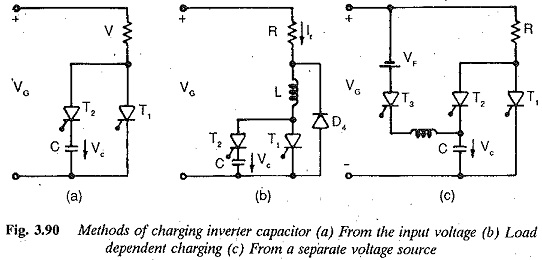
A negative voltage to the outgoing thyristor of an inverter is normally applied by, means of a capacitor via a commutating or auxiliary thyristor. For satisfactory commutation this capacitor must be charged to a sufficient voltage with correct polarity. The commutation circuit must have a provision to charge the capacitor. Basically the capacitor can be charged using
(a) the input voltage of the inverter.
(b) the load current of the inverter.
(c) a separate voltage source.
Sometimes a combination of these three methods can be employed. Figure 3.90 shows the three possibilities. The first case is illustrated in Fig. 3.90(a) and is suitable if the input voltage is constant. The second case is depicted in Fig. 3.90(b), in which the Charging a Capacitor is independent of input voltage, but on the load current. This circuit is not suitable for small currents, but has the advantage at higher currents of practically constant turn off time. The use of a separate voltage source to Charging a Capacitor is illustrated in Fig. 3.90(c). This method is suitable if there is a possibility of the input voltage falling below a certain value, or even disappearing.
To get an inverter which has an output voltage independent of the load current and which can provide the reactive current for the load, additional circuit elements are required. Sometimes diodes are connected antiparallel to the thyristors. These diodes enable one to use an inductive load on the inverter. They operate in the free wheeling as well as feed back modes. Commutating inductances are provided to prevent short circuits when both the incoming and outgoing thyristors conduct simultaneously. They also prevent the discharge of the commutating capacitance when commutation takes place through feed back diodes. Sometimes diodes are used in series with the thyristors to avoid the discharge of the commutating capacitance if the load contains a back emf or if there are sudden changes in the load. The commutating capacitor is connected between the diodes and the thyristors.