Voltage Source Inverter Control of Induction Motor:
Variable frequency and variable voltage supply for induction motor control can be obtained either from a voltage sourve inverter (VSI) or a cycloconverter. Voltage Source Inverter Control of Induction Motor are described here and cycloconverter fed drives.
VSI Induction Motor Drives:
Voltage Source Inverter Control of Induction Motor allows a variable frequency supply to be obtained from a dc supply. Fig. 6.37(a) shows a VSI employing transistors. Any other self-commutated device can be used instead of a transistor. Generally MOSFET is used in low voltage and low power inverters, IGET (insulated gate bipolar transistor) and power transistors are used up to medium power levels and GTO (gate turn off thyristor) and IGCT (insulated gate commutated thyristor) are used for high power levels.
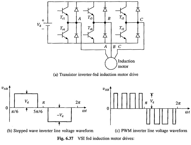
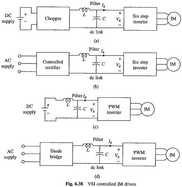
Voltage Source Inverter Control of Induction Motor can be operated as a stepped wave inverter or a pulse-width modulated (PWM) inverter. When operated as a stepped wave inverter, transistors are switched in the sequence of their numbers with a time difference of T/6 and each transistor is kept on for the duration T/2, where T is the time period for one cycle. Resultant line voltage waveform is shown in Fig. 6.37(b). Frequency of inverter operation is varied by varying T and the output voltage of the inverter is varied by varying dc input voltage. When supply is dc, variable dc input voltage is obtained by connecting a chopper between dc supply and inverter (Fig. 6.38(a)). When supply is ac, variable dc input voltage is obtained by connecting a controlled rectifier between ac supply and inverter (Fig. 6.38(b)). A large electrolytic filter capacitor C is connected in dc link to make inverter operation independent of rectifier or chopper and to filter out harmonics in dc link voltage.
Inverter output line and phase voltages are given by the following Fourier series:

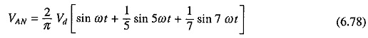
The rms value of the fundamental phase voltage
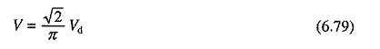
The torque for a given speed can be calculated by considering only fundamental component. The main drawback of stepped wave inverter is the large harmonics of low frequency in the output voltage. Consequently, an induction motor drive fed from a stepped wave inverter suffers from the following drawbacks:
- Because of low frequency harmonics, the motor losses are increased at all speeds causing derating of the motor.
- Motor develops pulsating torques due to fifth, seventh, eleventh and thirteenth harmonics which cause jerky motion of the rotor at low speeds.
- Harmonic content in motor current increases at low speeds. The machine saturates at light loads at low speeds due to high (Vlf ) ratio. These two effects overheat the machine at low speeds, thus limiting lowest speed to around 40% of base speed.
Harmonics are reduced, low frequency harmonics are eliminated, associated losses are reduced and smooth motion is obtained at low speeds also when inverter is operated as a pulse-width modulated inverter. Fig. 6.37(c) shows output voltage waveform for sinusoidal pulse-width modulation. Since output voltage can now be controlled by pulse-width modulation, no arrangement is required for the variation of input dc voltage, hence inverter can be directly connected when the supply is dc [Fig. 6.38(c)] and through a diode rectifier when supply is ac. [Fig. 6.38(d)].
The fundamental component in the output phase voltage of a PWM inverter operating with sinusoidal PWM is given by
where in is the modulation index.
The harmonics in the motor current produce torque pulsation and derate the motor. For a given harmonic content in motor terminal voltage, the current harmonics are reduced when the motor has higher leakage inductance, this reduces derating and torque pulsations. Therefore, when fed from Voltage Source Inverter Control of Induction Motor with large (compared to when fed from sinusoidal supply) leakage inductance are used.
Braking and Multiquadrant Operation of VSI Induction Motor Drives:
The power input into the.motor is given by
![]()
where
V = fundamental component of the motor phase voltage
Is = fundamental component of the motor phase current
Φ = phase angle between V and Is.
In motoring operation Φ < 90°, therefore Pin is positive i.e. power flows from the inverter to the machine. A reduction in frequency makes the synchronous speed less than the rotor speed and the relative speed between the rotor conductors and air-gap rotating field reverses. This reverses the rotor induced emf, rotor current and component of stator current which balances the rotor ampere turns. Consequently, angle Φ becomes greater than 90° and power flow reverses. The machine works as a generator feeding power into the inverter, which in turn feeds power into dc link by reversing the dc link current Id. Regenerative braking is obtained when the power flowing from the inverter to the dc link is usefully employed and dynamic braking is obtained when it is wasted in a resistance.
Dynamic Braking:
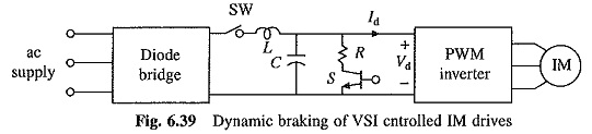
Let us first consider the dynamic braking of pulse-width modulated inverter drive of Fig. 6.38(d). With dynamic braking the drive will be as shown in Fig. 6.39. For dynamic braking, switch SW and a self-commutated switch (here transistor) in series with braking resistance RB connected across the dc link are added to the drive of Fig. 6.38(d). When operation of the motor is shifted from motoring to braking switch SW is opened. Generated energy flowing into the dc link charges the capacitor and its voltages rises. When it crosses a set value, switch S is closed, connecting the resistance across the link. The generated power and a part of energy stored in the capacitor flow into the resistance, and dc link voltage reduces. When it falls to its nominal value, S is opened. Thus by closing and opening switch S based on the value of dc link voltage, generated energy is dissipated in the resistance, giving dynamic braking. The dynamic braking operation of the drives of Figs. 6.38(a) to (c) can be obtained similarly.
Regenerative Braking :
Let us first consider the regenerative braking of pulse-width modulated (PWM) inverter drives of Figs. 6.38(c) and (d). In the drive of Fig. 6.38(c) when machine operation shifts from motoring to braking, Id reverses and flows into the dc supply feeding the energy to the source. Thus, the drive of Fig. 6.38(c) already has regenerative braking capability. In the case of the drive of Fig. 6.38(d), for regenerative braking, the power supplied to the dc link must be transferred to the ac supply. When the operation shifts from motoring to braking Id reverses but Vd remains in the same direction. Thus for regenerative braking capability, a converter capable of dealing with dc voltage of one polarity and dc current of either direction is required. A dual converter has this capability and was employed in the past. The recent drives use synchronous link converter (SLC) because it takes sinusoidal current at unity power factor from the ac source, both during motoring and braking operations. Thus while its performance is superior, it requires less devices than a dual converter. Principle of its operation is explained here.
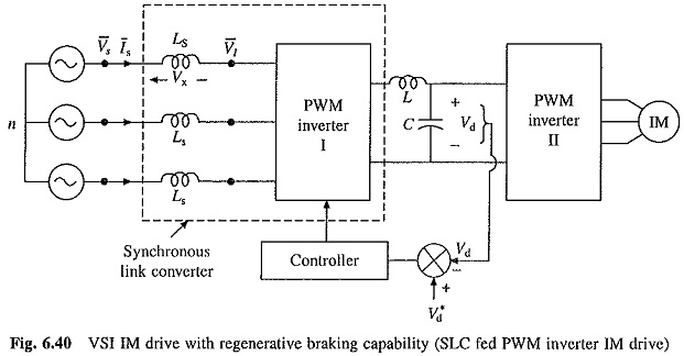
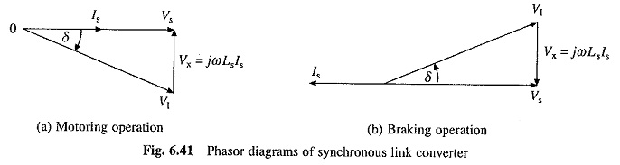
A regenerative drive with a SLC and PWM inverter is shown in Fig. 6.40. The inductors Ls and PWM inverter I constitute a SLC. PWM inverter I is operated to produce voltage VI of required magnitude and phase and with a low harmonic content, so that source current Is is nearly sinusoidal and in phase with Vs for motoring and 180° out of phase for braking, thus giving unity power factor. The phasor diagrams are shown in Figs. 6.41(a) and (b). For each value of Is, V1 of given phase and magnitude is required. This can be easily realized in sinusoidal pulse-width modulation (PWM). In sinusoidal PWM magnitude and phase of V1 depends on the magnitude and phase of modulation signal [1]. Therefore, V1 of given phase and magnitude can be produced by producing modulating signal of required magnitude and phase. Since VI is produced by PWM inverter, it does not contain low frequency harmonics. The inductor Ls filters out high frequency harmonics to produce a nearly sinusoidal source current Is. The phasor diagrams of Fig. 6.41 are similar to that of a synchronous machine. ThuS behavior of synchronous link converter is similar to that of a synchronous machine, hence it is called synchronous link converter.
When the drive of Fig. 6.40 is operating in steady state, power supplied (taken) by SLC must be equal to power taken (supplied) by PWM inverter II. Since the two work independent of each other, this is achieved by providing closed loop control of the dc link voltage. When the power supplied by SLC to the dc link equals the power taken by PWM inverter II, no energy will be supplied or taken from the capacitor C and its voltage will be constant and equal to the reference value Vd*. If now the load on IM is increased, power taken by PWM inverter II from the dc link will be higher than the power supplied by the SLC. Hence, the capacitor voltage Vd will fall below its reference value Vd*. The closed loop voltage control will increase the value of Is and therefore power supplied to the dc link. Hence, the dc link voltage will be brought back to the reference value.
Since SLC works as a boost converter, the closed loop control of dc link voltage provides the drive with ride through capability against a voltage sag and under voltage. When ac source voltage falls, the closed loop voltage control maintains the dc link voltage constant by increasing Is, and thus, the motor continues to be provided constant voltage, and therefore, produces same maximum power and torque.
The drive of Fig. 6.38(b) can have regenerative braking Capability by replacing controlled rectifier by a dual converter. The SLC cannot be used because it requires operation at a constant dc link voltage, whereas with six step inverter dc link voltage must be varied. The drive of Fig. 6.38(a) will have regenerative braking capability if a two quadrant chopper of Fig. 5.44 (capable of providing voltage of one polarity and current in either direction) is used.
Four Quadrant Operation :
Four quadrant operation can be obtained by any drive with braking (regenerative or dynamic) capability. A reduction of the inverter frequency, to make synchronous speed less than the motor speed, transfers the operation from quadrant I (forward motoring) to II (forward braking). The inverter frequency and voltage are progressively reduced as speed falls to brake the machine up to zero speed. Now phase sequence of the inverter output voltage is reversed by interchanging the tiring pulses between the switches of any two legs of the inverter, for example, between the pairs (Trl, Tr4) and (Tr3 and Tr6) in Fig. 6.37(a). This transfers the operation to quadrant HI (reverse motoring). The inverter frequency and voltage are increased to get the required speed in the reverse direction.