Current Source Inverter for Feeding Three Phase Motors:
In these type of Current Source Inverter, the controlled quantity is the current in the dc link. The current from the dc source remains constant at the controlled value, irrespective of the load and events in the inverter. The voltage across the load adjusts itself. The link current is maintained constant by means of a large link inductance. The capacitance in the dc link can be dispensed with.
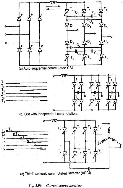
The dc link current is made to flow through the phases of the load alternately by controlling the inverter. These inverters are classified depending upon the commutation, and are shown in Fig .3.96. The control of the link current is achieved by means of a phase controlled rectifier on the line side. As the current is a controlled quantity, feed back diodes are not required. The Current Source Inverter shown in Fig. 3.96(a) employs individual commutation of phases. Auxiliary thyristors are used for commutation. The inverter shown in Fig. 3.96(b) employs sequential commutation and is rapidly gaining popularity. The diodes D1-D5 are used to prevent the discharging of capacitors through the load. They thus trap the charge on the capacitors. The inverter shown in Fig. 3.96(c) is a special case of an auto sequential commutated inverter.
The special features of current source inverters can be summarised as follows:
1. These inverters have load dependent commutation. As the load circuit, elements form a part of the commutation circuit, the inverter and the load (motor) must be matched with each other.
2. The inverter has a very simple configuration due to the absence of free wheeling diodes.
3. These are suitable for single motor operation.
4. Since the dc link contains only inductance two/four quadrant operation is straightforward. No additional converter is required on the line side.
5. A phase controlled rectifier is invariably required on the line side. The variable dc link voltage is converted to constant current by means of a high inductance.
6. Inverters employ forced commutation to give variable frequency currents
7. The currents are non-sinusoidal.
8. Converter grade thyristors are sufficient and thyristor utilisation is The capacitance used for commutation has a value which is a compromise between the voltage spikes and the highest operating frequency of the inverter.
9. The inverter can recover easily from commutation failure. In case of any fault, the link inductance prevents a fast rise of fault current so that by the time it reaches a large value, the fault can be suppressed.
10. There are stability problems at light loads and high speeds. A minimum current is required for satisfactory commutation.
11. Open loop operation is not possible, while operation over a wide range of frequencies is possible. Inverters have a sluggish dynamic response.
12. The power factor is poor due to phase control on the line side. When a three phase motor is used as a load on the inverter, the leakage reactance of the motor influences the harmonic voltage. It also causes voltage spikes during commutation. Being a parameter of the commutation circuit, it determines the time of commutation which limits the upper frequency. Therefore a motor must have low leakage reactance to have reduced harmonic voltages, small voltage spikes, and an increased range of speed control. The spikes in voltage influence the choice of the thyristors and affect motor insulation.