Voltage and Harmonic Control of Inverters:
Voltage and Harmonic Control of Inverters – In applying Inverters for motor control both V and f (keeping V/f constant) need to be varied. Further, the inverters apply essentially nonsinusoidal ac voltage to the motor.
External filter circuits cannot be employed due to the difficulty in operating inverters over a wide range of frequencies. It is therefore necessary to keep down the harmonic content of the ac output of the inverters.
While the inverter frequency is adjusted by varying the rate of thyristor firing, the Voltage and Harmonic Control of Inverters can be controlled in the following ways:
- Control of DC Input Voltage
- Chopper Control of DC Input Voltage
- Use of Inverters with Independent Voltage Control
1. Control of DC Input Voltage:
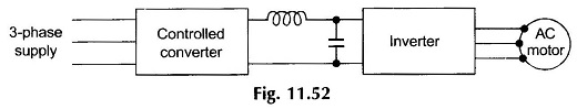
In this scheme a controlled converter supplies a variable dc voltage to the inverter as shown in Fig. 11.52. This method has the advantage of fixed harmonic voltage content in the inverter output. It presents the difficulty of doubtful reliability of the commutation circuitry at low values of the dc input as the commutation voltage in many inverter circuits is proportional to the dc input voltage.
2. Chopper Control of DC Input Voltage:
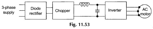
Here the fixed dc output voltage of an uncontrolled 3-phase full-wave bridge rectifier is controlled by a chopper circuit as shown in Fig. 11.53. This scheme has the advantage of good power factor at the ac input of the bridge rectifier and a faster voltage response owing to a smaller time-constant of the LC-filter on the output side of a high-frequency chopper. This scheme also suffers from the disadvantages of poor commutation (of inverter) at low input dc voltages and the fact that two power controllers have to be used in series.
3. Use of Inverters with Independent Voltage Control:
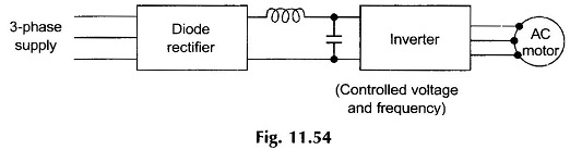
Inverter circuits (to be discussed later in this section) have been devised which permit independent control of both the output voltage and frequency. This method is illustrated schematically in Fig. 11.54.