Harmonic Reduction:
The output voltage waveform of an inverter is non-sinusoidal. It contains a rich harmonic content. The Harmonic Reduction cause additional losses and torque pulsations if a three phase motor is used as a load. These torque pulsations pose a problem at low speeds. Therefore it is necessary to improve the voltage waveform of an inverter and minimise the harmonic content. The following methods are employed to achieve this:
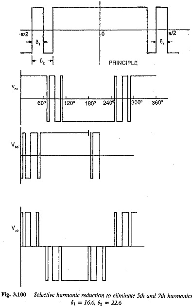
1. Reduction or even elimination of lower order harmonics by means of a switching process in the inverter. This method is called selective harmonic reduction and reduces the fifth and seventh harmonics to a minimum. The filter size decreases. The voltage waveform is shown in Fig. 3.100.
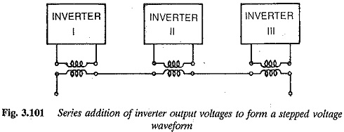
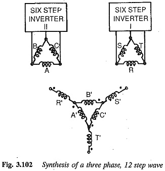
2. The number of pulses of the output wave can be increased to effectively reduce the harmonics. Several methods employed to increase the pulse number are shown in Figs 3.101, 3.102 and 3.103. A three phase output may be obtained using three single phase bridge converters as shown in Fig. 3.101. The resulting waveform has reduced harmonic content. The synthesis of the three phase waveform from two six-step inverters is illustrated in Fig. 3.102. The resultant twelve step waveform has a reduced harmonic content. The Harmonic Reduction which are multiples of three are eliminated. The interconnection of the outputs of six-step inverters to get a twelve stepped waveform is shown in Fig.
3.103. Multistepped waveform with reduced Harmonic Reduction can be obtained using multiple phase shifted inverters. It is possible to get 12, 18, 24, … stepped waveform using suitable number of inverters and phase shift.
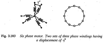
3. Increasing the number of phases minimises the harmonic content. A twelve pulse inverter provides an output voltage free from fifth and seventh harmonics. The principle of the method and the waveforms are given in Fig. 3.103. Using this method, harmonics of order 5, 7, 17, 19 Can be eliminated without affecting harmonics order of 11, 13, 23, 25, etc.
4. Several Harmonic Reduction can be eliminated by combining the phase displaced outputs of two inverters. This method has poor inverter utilisation and is not used.
5.Multiple pulse width control —By increasing the switching of the inverter voltage, waveforms having several pulses can be obtained, in which the content of lower order harmonics is minimised. The voltage waveforms are shown in Fig. 3.104.
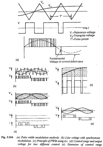
6. Pulse width modulation is also used to minimise the lower order harmonics. Using sinusoidal modulation it is possible to get an output voltage waveform which has a very low harmonic content, as shown in Fig. 3.104. In this process, the pulse duration is sinusoidally modulated. The modulation process and output voltage are shown in Fig. 3.104.