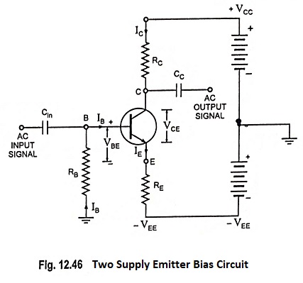
Two Supply Emitter Bias Circuit:
From the stability point of view, this two supply emitter bias circuit is the best of all already discussed circuits, but it has one drawback that it requires two power supplies or batteries or it requires one-split supply (dc power supply with a central point available).
Applying Kirchhoff’s second law around the circuit loop starting from VEE and containing RE and RB
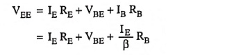
and IC ≈ IE for most practical purposes
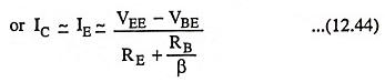
The above equation provides almost an exact expression for IE. It can further be simplified by realizing that in most of the cases VBE is negligible in comparison to VEE. Also RB is chosen quite small so that RB/β is also negligible in comparison to RE
So
![]()
The above equation may be used to calculate the value of IE for rough calculations at first instance but for exact value of IE the former expression be used.
The approximate expression for IE also suggests that all the VEE supply is dropped across emitter resistance RE. Therefore, the emitter terminal E is at ground potential for all practical purposes.
The collector-to-emitter voltage, VCE is given as
![]()
since emitter is practically at ground potential.
Thus point Q is established.
From the expression,
![]()
we see that emitter or collector current is independent of variation of temperature as β and VBE do not appear in the said expression.
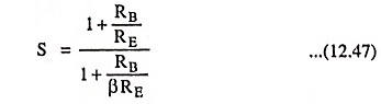
For this two supply emitter bias circuit stability factor is given as