Synchronous Speed on Variable Frequency Supply:
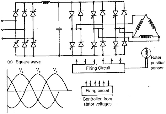
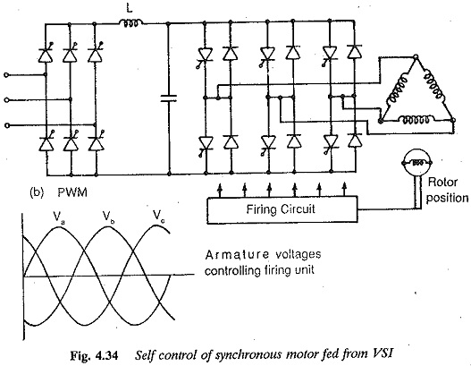
As has already been discussed, the speed of a synchronous motor can be varied by supply frequency variation similar to an induction motor. The applied voltage must be varied in this case also to have the maximum torque capability and to avoid saturation at all frequencies. A Synchronous Speed can receive its variable voltage, variable frequency supply from a cycloconverter or a dc link converter. The dc link converter can have a voltage source inverter to feed impressed voltages or a current source inverter to feed impressed currents. Further, the voltage source inverter can be a square wave inverter with variable link voltage or a PWM inverter with constant link voltage. These types are depicted in Fig. 4.34. In all these cases self control can be employed with the motor in the CLM mode which imparts a very good steady-state and dynamic behaviour similar to a dc motor. But machine commutation may not be always possible.
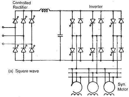
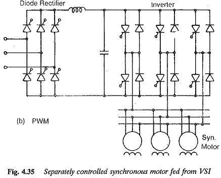
A separate control of the inverter feeding a synchronous motor can also be used. In this case the speed of the motor is determined from an external frequency obtained from a crystal oscillator (Fig. 4.35). The performance of the motor is similar to a conventional Synchronous Speed with problems of hunting for sudden changes of load. Multimotor operation is possible here. This is seldom used with inverter feeding.
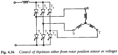
Principle of self control:Self controlled mode of a Synchronous Speed facilitates unique positioning of stator voltage vector and rotor flux vector. This is similar to a dc motor where the armature mmf and field mmf are in space quadrature by proper positioning of the brushes in the neutral zone. The principle of self control can be explained for a three phase motor, referring to Fig. 4.36. The three windings of a three phase synchronous motor are 120° away from each other in space and are connected in star. These windings are connected to a dc supply through a thyristor inverter having thyristors T1 and T6. The rotor position decides the thyristors to be fired in the sequence. Depending upon the thyristors conducting, the currents in the windings flow. These produce an mmf fixed in space till the other thyristor in the sequence is fired and is ahead of the rotor mmf. The stator mmf changes its position when the next thyristor is fired. Thus a dc link current flows through the phases of the motor alternately as the inverter is controlled. These currents effectively produce an mmf which rotates by two pole pitches by the time all the thyristors are fired once in the sequence. The rotor carrying a dc excitation produces a field mmf which rotates with the rotor. The angle between the stator mmf and rotor mmf decreases owing to the rotation. When once the angle takes the value of 60°, the next thyristor in the sequence is fired, so that the stator mmf jumps by 60°, making the angle between the mmfs 120°. Thus at the start of conduction of a pair of thyristors stator windings, the mmfs have an angle of 120° which slowly decreases as the field rotates. When the angle reaches 60° the next two windings conduct as the next thyristor is fired to bring the angle to a value of 120°. Thus the angle between the mmfs changes from 120° to 60°.
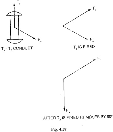
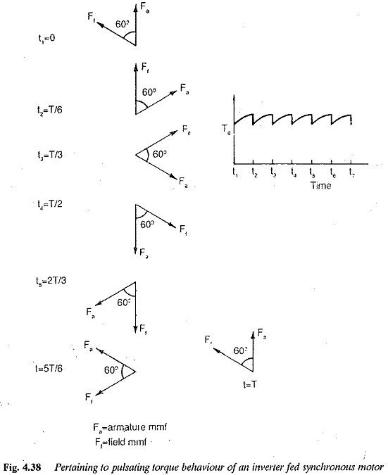
Referring to Fig. 4.37 at the instant the phases S and R start conduction due to conduction of T1 and T6, the angle between the mmfs is 120°. Due to rotation it slowly decreases and at the instant t2 when the angle is 60°, T2 is fired. The commutation takes place during which T1 stops conduction and T2 takes over. The stator mmf has shifted to a new position by 60° making the angle again 120°. Similar operations repeat at firing of each thyristor (Fig. 4.37). Following this the torque developed by the motor is not a constant one but has pulsations varying between a maximum and 0.86 of maximum values (Fig. 4.38). These pulsations can be reduced to a minimum by increasing the pulse number of the inverter. In the case of dc motors the pulsations are almost absent because of a large number of commutator segments which correspond to pulses of the inverter. The brushes on the commutator decide the commutation instants. By virtue of their lying in the neutral zone the angle between the mmfs is maintained at 90°. In the case of a self controlled motor the commutation instants are decided by rotor position or synchronisation of machine voltages, as explained previously. The inverter here can be considered as a six segment commutator.
In self controlled mode the power factor can be maintained at the desired value by using a closed loop control. A constant air gap flux can be achieved by independent field control. Field weakening exists, similar to the case of an induction motor, when the inverter voltage and field current have reached their rated values.
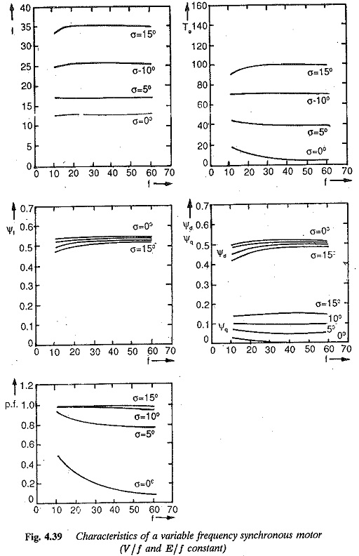
In a Synchronous Speed on a variable frequency supply, several modes of control exist. Both terminal voltage and excitation voltage can be varied proportional to frequency. V/f and E/f are constant. The value of E/f is constant if field current is held at a constant value. If the applied voltage is varied proportional to frequency and the effect of stator resistance is neglected, constant flux operation results in the basic speed range. However, at low frequencies the stator resistance drop becomes comparable to the applied voltage and hence a correction is required to compensate for the resistance drop. The motor has a speed-torque curve similar to that of a separately excited dc motor. Also, when the effects of stator resistance are compensated, it can be easily seen that the stator current is independent of supply frequency (Fig. 4.39).
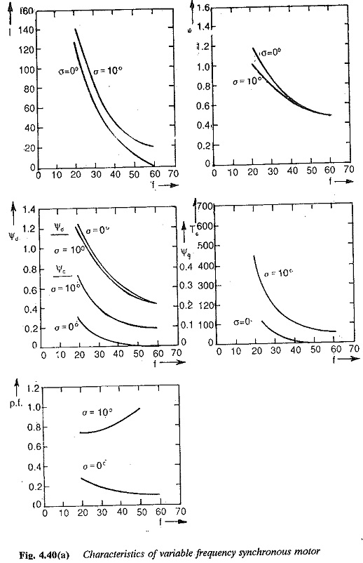
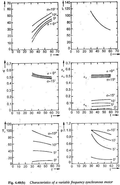
A control of the motor with constant V and E/f on the other hand, imparts a series characteristic to the motor which makes it suitable for traction purposes. The problems of saturation have to be taken care of at low frequencies (Fig. 4.40).
When fed from a VSI the load commutation is not possible. As the power factor can be controlled by field excitation, UPF operation of the motor reduces the size of the inverter and its commutation circuit. The armature copper losses are also reduced.
The above controls can be realised with PWM inverters also, in which the voltage control is achieved in the inverter itself. By this the speed range is extended up to zero; the harmonic content of the stator current decreases. Consequently, the torque pulsations are also decreased.
An examination of the control to keep V/f and E/f constant shows that the armature current is independent of frequency when the effects of resistance have been corrected, particularly at low frequencies. This leads to a simple and straightforward control of stator current to maintain constant flux in the motor. This makes the operation of a synchronous motor for a current source inverter feasible. Self controlled CLM operation and load commutation are possible. As has already been stated, commutation assistance is required at low speeds. Forced commutation may be employed at low frequencies. The circuit becomes simple and less expensive if the p.f. is maintained at unity. Field regulation may also be employed to keep the air gap flux constant. Current control is advantageous as it assures reserve voltage. However when the frequency reaches the rated value, this reserve is not present and the field weakening starts. A motor for CSI operation should invariably have damper windings. The subtransient (leakage) reactance is effective during commutation. This must be as small as possible to limit voltage spikes. The dampers actually decrease this reactance. The overlap decreases. The control sometimes requires force commutation in which case p.f. can be controlled to unity in view of the advantages discussed already. The field mmf required is however greater than that of an induction motor due to armature reaction.
A cycloconverter can also be used to provide variable frequency supply to a Synchronous Speed. This can be either line commutated or machine commutated. When line commutated there exists a limitation on the output frequency. The speed variation can be in the range 0-1/3 of base speed. When machine commutation is employed the speed range can be 10% —100% base speed. The machine must be overexcited. Therefore, when supplied from a cycloconverter for lower speed range it can be line commutated and for upper speed range machine commutation may be employed. In both the cases self control is possible.
The overlap angle is called the margin angle of commutation. If this angle is very small and is less than the turn off angle of the thyristor, commutation failure occurs. Safe commutation is assured if this angle has a minimum value equal to the turn off angle of the thyristor. The type of sensing influences the margin angle. When voltage sensing is used the firing angle of the inverter thyristors may be constant. The angle of overlap increases as the dc link current increases. Therefore at large values of link current the margin angle decreases and this may cause failure of commutation at a particular current. To avoid this the load angle of firing has to be simultaneously increased. When this is done certain disadvantages, such as increased torque pulsations at low speeds, poor power factor on line side, and poor efficiency would occur.
To have better performance with respect to the above quantities, the firing angle is controlled such that the margin angle remains constant at the minimum value required and ensures safe commutation at all operating points. The control can be employed with self controlled Synchronous Speed using either rotor position sensing or voltage sensing using closed loop control, to achieve this. The margin angle kept constant at steady-state may not remain constant under dynamic conditions.
The advantages of margin angle control can be summarized:
1.Commutation failure is prevented.
2.The maximum power output can be increased by simultaneous control of field current to compensate for armature reaction. This improves the overload capacity of the motor.
3.There is improvement in power factor.
4.The torque pulsations under light load conditions are reduced. The ripple content of the dc link current also decreases.
However, a disadvantage of the method, is a limited speed range with a limit on the upper speed. To increase the upper speed limit, margin time control is employed. This improves the performance of the drive.